Lexus ES: Removal
REMOVAL
CAUTION / NOTICE / HINT
The necessary procedures (adjustment, calibration, initialization, or registration) that must be performed after parts are removed and installed, or replaced during front disc brake pad removal/installation are shown below.
Necessary Procedures After Parts Removed/Installed/Replaced (for HV Model)|
Replaced Part or Performed Procedure |
Necessary Procedure |
Effect/Inoperative Function when Necessary Procedure not Performed |
Link |
|---|---|---|---|
| *: When performing learning using the Techstream.
Click here |
|||
|
Auxiliary battery terminal is disconnected/reconnected |
Perform steering sensor zero point calibration |
Lane Control System (for HV Model) |
|
|
Pre-collision System (for HV Model) |
|||
|
Parking Support Brake System (for HV Model)* |
|||
|
Lighting System (for HV Model) |
|||
|
Memorize steering angle neutral point |
Parking Assist Monitor System (for HV Model) |
|
|
|
Panoramic View Monitor System (for HV Model) |
|
||
|
Initialize power trunk lid system |
Power Trunk Lid System (for HV Model) |
|
|
NOTICE:
- Immediately after installing the brake pads, the braking performance may be reduced. Always perform a road test in a safe place while paying attention to the surroundings.
- After replacing the front disc brake pads, the brake pedal may feel soft due to clearance between the front disc brake pads and front disc. Depress the brake pedal several times until the brake pedal feels firm.
- After replacing the front disc brake pads, always perform a road test to check the braking performance and check for vibrations.
- When the brake pedal is first depressed after replacing the brake pads or pushing back the disc brake piston, DTC C1214 may be stored. As there is no malfunction, clear the DTC. (for HV Model)
- While the auxiliary battery is connected, even if the power switch is off, the brake control system activates when the brake pedal is depressed or any door courtesy switch turns on. Therefore, when servicing the brake system components, do not operate the brake pedal or open/close the doors while the auxiliary battery is connected. (for HV Model)
- After the power switch is turned off, the radio receiver assembly records various types of memory and settings. As a result, after turning the power switch off, make sure to wait at least 85 seconds before disconnecting the cable from the negative (-) auxiliary battery terminal. (for HV Model Audio and Visual System)
- After the power switch is turned off, the radio receiver assembly records various types of memory and settings. As a result, after turning the power switch off, make sure to wait at least 85 seconds before disconnecting the cable from the negative (-) auxiliary battery terminal. (for HV Model Navigation System)
HINT:
- Use the same procedure for the RH side and LH side.
- The following procedure is for the LH side.
PROCEDURE
1. PRECAUTION (for HV Model)
NOTICE:
After turning the power switch off, waiting time may be required before disconnecting the cable from the negative (-) auxiliary battery terminal. Therefore, make sure to read the disconnecting the cable from the negative (-) auxiliary battery terminal notices before proceeding with work.
2. DISABLE BRAKE CONTROL (for HV Model)
Click here .gif)
3. REMOVE FRONT WHEEL
Click here
4. REMOVE FRONT DISC BRAKE PAD
CAUTION:
- Be careful not to get pinched by the front disc brake cylinder assembly or other parts when removing the front disc brake pads.
- After lifting up the front disc brake cylinder assembly, secure it in
place before performing any work on it.
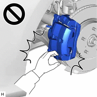
- The front disc brake cylinder assembly could fall, pinching hands or fingers and causing injury.
|
(a) Hold the front disc brake cylinder slide pin (lower side) and remove the bolt. NOTICE: Do not kink or damage the brake line. |
|

(b) Pull the front disc brake cylinder assembly upward.
|
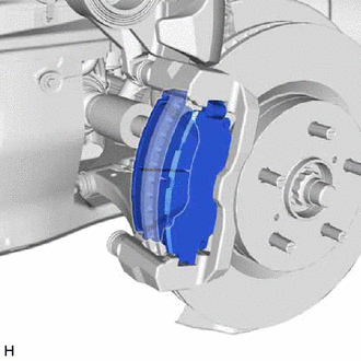
(c) Remove the 2 front disc brake pads from the front disc brake cylinder mounting. |
|
5. REMOVE FRONT DISC BRAKE ANTI-SQUEAL SHIM KIT
(a) Remove the front No. 1 disc brake anti-squeal shim and front No. 2 disc brake anti-squeal shim from each front disc brake pad.
|
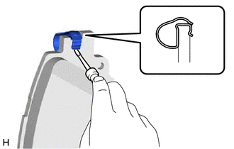
(b) Using a screwdriver, remove the front disc brake pad wear indicator plate from each front disc brake pad. |
|
READ NEXT:
 Installation
INSTALLATION
CAUTION / NOTICE / HINT
NOTICE:
Immediately after installing the brake pads, the braking performance
may be reduced. Always perform a road test in a safe place while paying
Front Side Marker Light Bulb
Components
COMPONENTS
ILLUSTRATION
*1
FRONT SIDE MARKER LIGHT BULB
*2
REAR FENDER SPLASH SHIELD SUB-ASSEMBLY
*3
FRONT FEN
Front Turn Signal Light Bulb
Components
COMPONENTS
ILLUSTRATION
*1
FRONT TURN SIGNAL LIGHT BULB
*2
REAR FENDER SPLASH SHIELD SUB-ASSEMBLY
*3
FRONT FEN
SEE MORE:
System Description
SYSTEM DESCRIPTION DISC PLAYER OUTLINE (a) A disc player uses a laser pickup to read digital signals recorded on a disc. By converting the digital signals to analog, it can play music and audio. CAUTION: Do not look directly at the laser pickup because the disc player uses an invisible laser beam. B
PBD/PTL Closer Switch (B2251)
DESCRIPTION DTC B2251 is output if there is a malfunction in the half latch switch circuit of the luggage door closer assembly. DTC No. Detection Item DTC Detection Condition Trouble Area B2251 PBD/PTL Closer Switch When luggage door is opening or closing, malfunction occurs in half
