Lexus ES: Lost Communication with Airbag System Control Module Circuit Short to Ground (P310711)
DESCRIPTION
The hybrid vehicle control ECU detects a problem in the collision signal line from the airbag ECU assembly and alerts the driver.
| DTC No. | Detection Item | DTC Detection Condition | Trouble Area | MIL | Warning Indicate |
|---|---|---|---|---|---|
| P310711 | Lost Communication with Airbag System Control Module Circuit Short to Ground | Short to ground in the communication circuit: Communication from the airbag ECU assembly stopped and Circuit Low has been detected for a certain period. (1 trip detection logic) |
| Does not come on | Master Warning Light: Comes on |
| DTC No. | Data List |
|---|---|
| P310711 | Airbag Status (Collision) |
CONFIRMATION DRIVING PATTERN
HINT:
After repair has been completed, clear the DTCs and then check that the vehicle has returned to normal by performing the following All Readiness check procedure.
Click here .gif)
- Connect the Techstream to the DLC3.
- Turn the power switch on (IG) and turn the Techstream on.
- Clear the DTCs (even if no DTCs are stored, perform the clear DTC procedure).
- Turn the power switch off and wait for 2 minutes or more.
- Turn the power switch on (IG) and turn the Techstream on.
- With power switch on (IG) and wait for 2 minutes or more.
- Enter the following menus: Powertrain / Hybrid Control / Utility / All Readiness.
-
Check the DTC judgment result.
HINT:
- If the judgment result shows NORMAL, the system is normal.
- If the judgment result shows ABNORMAL, the system has a malfunction.
- If the judgment result shows INCOMPLETE or N/A, perform driving pattern again.
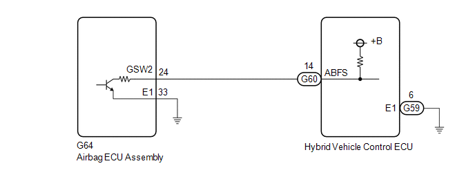
WIRING DIAGRAM
PROCEDURE
| 1. | CHECK DTC OUTPUT (SRS AIRBAG) |
(a) Connect the Techstream to the DLC3.
(b) Turn the power switch on (IG).
(c) Enter the following menus: Body Electrical / SRS Airbag / Trouble Codes.
(d) Check for DTCs.
Body Electrical > SRS Airbag > Trouble Codes| Result | Proceed to |
|---|---|
| Airbag system DTCs are not output. | A |
| Airbag system DTCs are output. | B |
(e) Turn the power switch off.
| B | .gif) | GO TO DTC CHART (AIRBAG SYSTEM) |
|
.gif)
| 2. | CHECK AIR BAG ECU ASSEMBLY (CHECK WAVEFORM) |
(a) Connect an oscilloscope between the hybrid vehicle control ECU terminals specified in the table below.
(b) Turn the power switch on (READY).
| (c) Measure the waveform.
|
|
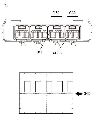
(d) Turn the power switch off.
| B | | GO TO STEP 6 |
|
| 3. | CLEAR DTC |
Click here
|
| 4. | CHECK DTC OUTPUT (HYBRID CONTROL) |
(a) Connect the Techstream to the DLC3.
(b) Turn the power switch on (IG).
(c) Enter the following menus: Powertrain / Hybrid Control / Trouble Codes.
(d) Check for DTCs.
Powertrain > Hybrid Control > Trouble Codes| Result | Proceed to |
|---|---|
| P310711 is not output. | A |
| P310711 is output. | B |
(e) Turn the power switch off.
| B | | REPLACE HYBRID VEHICLE CONTROL ECU |
|
| 5. | CHECK FOR INTERMITTENT PROBLEMS |
Click here
| OK | | REPLACE HYBRID VEHICLE CONTROL ECU |
| NG | | REPAIR OR REPLACE MALFUNCTIONING PARTS, COMPONENT AND AREA |
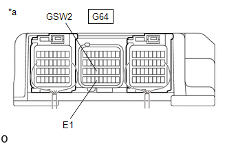
| 6. | CHECK AIR BAG ECU ASSEMBLY |
(a) Disconnect the G64 airbag ECU assembly connector.
| (b) Measure the resistance according to the value(s) in the table below. Standard Resistance:
|
|
(c) Reconnect the G64 airbag ECU assembly connector.
| NG | | REPLACE AIR BAG ECU ASSEMBLY |
|
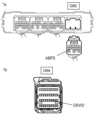
| 7. | CHECK HARNESS AND CONNECTOR (HYBRID VEHICLE CONTROL ECU - AIRBAG ECU ASSEMBLY) |
(a) Disconnect the G60 hybrid vehicle control ECU connector.
(b) Disconnect the G64 airbag ECU assembly connector.
| (c) Measure the resistance according to the value(s) in the table below. Standard Resistance:
|
|
(d) Reconnect the G64 airbag ECU assembly connector.
(e) Reconnect the G60 hybrid vehicle control ECU connector.
| OK | | REPLACE HYBRID VEHICLE CONTROL ECU |
| NG | | REPAIR OR REPLACE HARNESS OR CONNECTOR |
READ NEXT:
 Lost Communication with Airbag System Control Module Circuit Short to Auxiliary Battery or Open (P310715)
DESCRIPTION Refer to the description for DTC P310711. Click here DTC No. Detection Item DTC Detection Condition Trouble Area MIL Warning Indicate P310715 Lost Communication with A
Lost Communication with Airbag System Control Module Signal Plausibility Failure (P310764)
DESCRIPTION Refer to the description for DTC P310711. Click here DTC No. Detection Item DTC Detection Condition Trouble Area MIL Warning Indicate P310764 Lost Communication with A
Lost Communication with Drive Motor Control Module "A" from Hybrid/EV Control Module Missing Message (P312387)
DESCRIPTION Refer to the description for P0D2D16. Click here The MG ECU, which is built into in the inverter with converter assembly, controls motor (MG2) based on commands from the hybrid vehicle c
SEE MORE:
The Display of the Multi-display does not Switched
DESCRIPTION The multi-display receives a signal from the clearance warning ECU assembly to change the display screen. WIRING DIAGRAM PROCEDURE 1. CHECK HARNESS AND CONNECTOR (CLEARANCE WARNING ECU ASSEMBLY - MULTI-DISPLAY ASSEMBLY) (a) Disconnect the N41 clearance warning ECU assembly conn
Parts Location
PARTS LOCATION ILLUSTRATION *1 INSTRUMENT PANEL JUNCTION BLOCK ASSEMBLY - DCM FUSE - ECU-IG2 NO. 3 FUSE *2 DLC3 *3 AIRBAG ECU ASSEMBLY *4 DCM (TELEMATICS TRANSCEIVER) - MOBILEPHONE BATTERY ILLUSTRATION *1 FRONT NO. 2 SPEAKER ASSEMBLY (RH) *2 TELEPHONE MICROPHONE ASSE
