Lexus ES: Installation
INSTALLATION
CAUTION / NOTICE / HINT
HINT:
- Use the same procedure for the RH side and LH side.
- The following procedure is for the LH side.
PROCEDURE
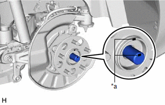
1. INSTALL REAR AXLE HUB AND BEARING ASSEMBLY
| (a) Install the rear axle hub and bearing assembly and rear disc brake dust cover sub-assembly to the rear drive shaft assembly. NOTICE: Align the matchmarks on the rear drive shaft assembly and rear axle hub and bearing assembly. |
|
(b) Install the rear axle hub and bearing assembly and rear disc brake dust cover sub-assembly to the rear axle carrier sub-assembly with the 4 bolts.
Torque:
90 N·m {918 kgf·cm, 66 ft·lbf}
2. INSTALL REAR DISC
Click here .gif)
3. INSTALL REAR DISC BRAKE CALIPER ASSEMBLY
Click here
4. TEMPORARILY INSTALL REAR AXLE SHAFT NUT
(a) Clean the threaded parts on the rear drive shaft assembly and a new rear axle shaft nut using non-residue solvent.
NOTICE:
- Be sure to perform this work even when using a new rear drive shaft assembly.
- Keep the threaded parts free of oil and foreign matter.
(b) Using a 30 mm deep socket wrench, temporarily install the rear axle shaft nut.
Torque:
216 N·m {2203 kgf·cm, 159 ft·lbf}
NOTICE:
Stake the rear axle shaft nut after inspecting for looseness and runout in the following steps.
HINT:
Keep depressing the brake pedal to prevent the rear drive shaft assembly from rotating.
5. SEPARATE REAR DISC BRAKE CALIPER ASSEMBLY
Click here
6. REMOVE REAR DISC
Click here
7. INSPECT REAR AXLE HUB BEARING LOOSENESS
Click here
8. INSPECT REAR AXLE HUB RUNOUT
Click here
9. INSTALL REAR DISC
Click here
10. INSTALL REAR DISC BRAKE CALIPER ASSEMBLY
Click here
11. STAKE REAR AXLE SHAFT NUT
| (a) Using a chisel and hammer, stake the rear axle shaft nut. |
|
.png)
12. INSTALL REAR SKID CONTROL SENSOR
(a) Install the rear skid control sensor to the rear axle carrier sub-assembly with the bolt.
Torque:
8.5 N·m {87 kgf·cm, 75 in·lbf}
NOTICE:
- Keep the tip of the rear skid control sensor and installation hole free of foreign matter.
- Firmly insert the rear skid control sensor body into the rear axle carrier sub-assembly before tightening the bolt.
- After installing the rear skid control sensor to the rear axle carrier sub-assembly, make sure that there is no clearance between the rear skid control sensor stay and rear axle carrier sub-assembly. Also make sure that no foreign matter is stuck between the parts.
13. CONNECT NO. 2 PARKING BRAKE WIRE ASSEMBLY
(a) Connect the No. 2 parking brake wire assembly connector to the parking brake actuator assembly.
(b) Connect the No. 2 parking brake wire assembly connector to the rear skid control sensor.
14. INSTALL REAR WHEEL
Click here
15. CHECK FOR SPEED SENSOR SIGNAL
Click here
READ NEXT:
 On-vehicle Inspection
ON-VEHICLE INSPECTION CAUTION / NOTICE / HINT HINT:
Use the same procedure for the RH side and LH side.
The following procedure is for the LH side.
PROCEDURE 1. REMOVE REAR WHEEL Click here
Removal
REMOVAL CAUTION / NOTICE / HINT HINT:
Use the same procedure for the RH side and LH side.
The following procedure is for the LH side.
PROCEDURE 1. REMOVE REAR WHEEL Click here 2. REMOVE REAR
SEE MORE:
VC Output Circuit
DESCRIPTION The ECM constantly generates a 5 V power source voltage from the battery voltage supplied to the +B, +B2 (BATT) terminals to operate the microprocessor. The ECM also provides this power to the sensors through the VC output circuit. When the VC circuit has a short circuit, the microproce
Fail-safe Chart
FAIL-SAFE CHART Automatic Cancel Control (a) When the vehicle is being driven in constant speed control mode and any of the following malfunctions occur, control of vehicle speed by the dynamic cruise control system is canceled. Auto Cancel Condition Multi-information Display Master Warning L
