Lexus ES: Components
COMPONENTS
ILLUSTRATION
.png)
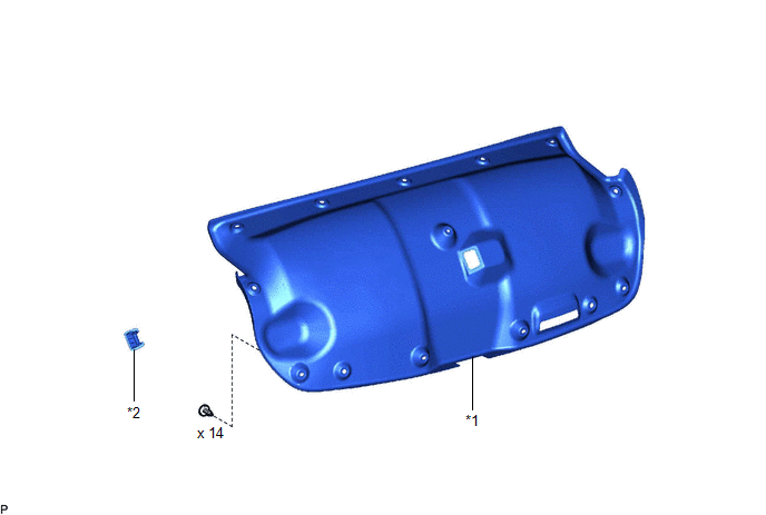
| *1 | LUGGAGE COMPARTMENT FLOOR MAT | *2 | SPARE WHEEL COVER TRAY |
ILLUSTRATION
.png)
| *1 | REAR FLOOR FINISH PLATE | *2 | LUGGAGE HOLD BELT STRIKER ASSEMBLY |
ILLUSTRATION
| *1 | LUGGAGE COMPARTMENT DOOR COVER | *2 | LUGGAGE LOCK CONTROL CABLE PLATE |
ILLUSTRATION
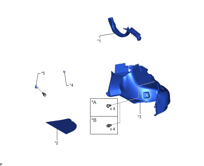
| *A | for Type A | *B | for Type B |
| *1 | LUGGAGE COMPARTMENT DOOR HINGE COVER RH | *2 | LUGGAGE COMPARTMENT TRIM COVER RH |
| *3 | LUGGAGE COMPARTMENT TRIM INNER COVER RH | *4 | ROPE HOOK |
| *5 | LUGGAGE HOLD BELT STRIKER ASSEMBLY | - | - |
ILLUSTRATION
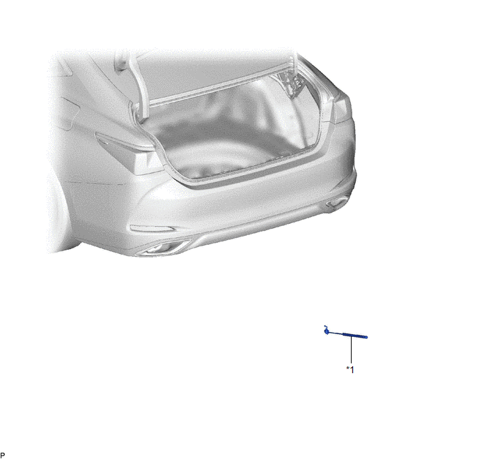
| *1 | LUGGAGE COMPARTMENT DOOR SUPPORT ASSEMBLY | - | - |
READ NEXT:
 Removal
REMOVAL CAUTION / NOTICE / HINT CAUTION: If the luggage compartment door support assembly is removed, the luggage compartment door will slam shut. Make sure to support the luggage compartment door by
Installation
INSTALLATION CAUTION / NOTICE / HINT CAUTION: After installing the luggage compartment door support assembly, use your hand to open and close the luggage door. Make sure the luggage door can open and
Disposal
DISPOSAL PROCEDURE 1. DISPOSE OF LUGGAGE COMPARTMENT DOOR SUPPORT ASSEMBLY (a) Secure the luggage compartment door support assembly horizontally in a vise with the piston rod pulled out.
SEE MORE:
Removal
REMOVAL CAUTION / NOTICE / HINT The necessary procedures (adjustment, calibration, initialization, or registration) that must be performed after parts are removed and installed, or replaced during shift paddle switch (transmission shift switch assembly) removal/installation are shown below. Necessar
Short circuit in Power source circuit (C13A1)
DESCRIPTION C13A1 is stored if the power supply relay in the parking brake ECU assembly has a short circuit. C13A1 is stored if the power switch is off and a voltage of 2.5 V or higher is applied to the IG terminal and an electric parking brake switch assembly malfunction or wire harness malfunction
© 2016-2026 Copyright www.lexguide.net
