Lexus ES: Installation
INSTALLATION
PROCEDURE
1. INSTALL NAVIGATION ANTENNA BRACKET
2. INSTALL NAVIGATION ANTENNA ASSEMBLY
(a) Engage the 6 guides and 2 claws to install the navigation antenna assembly as shown in the illustration.
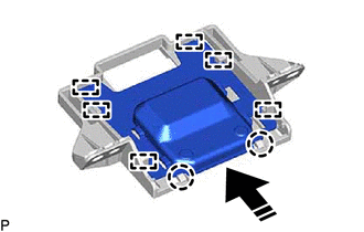
.png) | Install in this Direction |
3. INSTALL NAVIGATION ANTENNA ASSEMBLY WITH BRACKET
(a) Install the navigation antenna assembly with bracket with the 2 screws.
(b) Engage the 2 claws.
(c) Connect the connector.
4. INSTALL NO. 3 HEATER TO REGISTER DUCT
Click here .gif)
5. INSTALL DEFROSTER NOZZLE ASSEMBLY
Click here
6. INSTALL NO. 2 SIDE DEFROSTER NOZZLE DUCT
Click here
7. INSTALL INSTRUMENT PANEL SAFETY PAD SUB-ASSEMBLY
Click here
READ NEXT:
 Removal
REMOVAL CAUTION / NOTICE / HINT The necessary procedures (adjustment, calibration, initialization, or registration) that must be performed after parts are removed and installed, or replaced during nav
Components
COMPONENTS ILLUSTRATION *1 CENTER INSTRUMENT CLUSTER FINISH PANEL SUB-ASSEMBLY *2 INSTRUMENT PANEL FINISH PANEL END LH *3 INSTRUMENT PANEL FINISH PANEL END RH *4 REAR UPPER CONSOLE
SEE MORE:
Freeze Frame Data
FREEZE FRAME DATA FREEZE FRAME DATA/INFORMATION (a) Using the Techstream, check the vehicle condition (ECU, sensor) when the brake system operates or a DTC is output. CHECK FREEZE FRAME DATA AND INFORMATION WHEN DTC WAS STORED (a) Freeze Frame Data is stored when a DTC is output. (b) Once Freeze Fra
On-vehicle Inspection
ON-VEHICLE INSPECTION CAUTION / NOTICE / HINT CAUTION: Do not remove the radiator cap sub-assembly while the engine and radiator assembly are still hot. Pressurized, hot engine coolant and steam may be released and cause serious burns. PROCEDURE 1. CHECK RADIATOR CAP SUB-ASSEMBLY CAUTION: Do not re
© 2016-2026 Copyright www.lexguide.net
