Lexus ES: Rear Sensor Communication Malfunction (C1AED)
DESCRIPTION
This DTC is stored when there is an open or short circuit in the communication line between the rear sensors and the ECU, or when there is a malfunction in a rear sensor.
| DTC No. | Detection Item | DTC Detection Condition | Trouble Area |
|---|---|---|---|
| C1AED | Rear Sensor Communication Malfunction | An open or short circuit in the communication line between the rear sensors and ECU or a malfunction in a rear sensor during initialization mode after the engine switch is turned on (IG). |
|
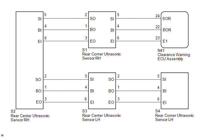
WIRING DIAGRAM
PROCEDURE
| 1. | INITIALIZE REAR CENTER ULTRASONIC SENSOR AND REAR CORNER ULTRASONIC SENSOR |
(a) Initialize the rear center ultrasonic sensor and rear corner ultrasonic sensor.
Click here .gif)
|

| 2. | CHECK DTC OUTPUT (C1AED) |
(a) Check for DTCs.
Body Electrical > Advanced Parking Guidance/ICS/Intuitive P/A > Trouble Codes(b) Clear the DTCs.
Body Electrical > Advanced Parking Guidance/ICS/Intuitive P/A > Clear DTCs(c) Recheck for DTCs.
Body Electrical > Advanced Parking Guidance/ICS/Intuitive P/A > Trouble Codes| Result | Proceed to |
|---|---|
| DTC C1AED is output | A |
| No DTCs are output | B |
| B |  | USE SIMULATION METHOD TO CHECK |
|
| 3. | CHECK HARNESS AND CONNECTOR (CLEARANCE WARNING ECU ASSEMBLY - REAR CORNER ULTRASONIC SENSOR RH) |
(a) Disconnect the N41 clearance warning ECU assembly connector.
(b) Disconnect the S1 rear corner ultrasonic sensor RH.
(c) Measure the resistance according to the value(s) in the table below.
Standard Resistance:
| Tester Connection | Condition | Specified Condition |
|---|---|---|
| N41-22 (BOR) - S1-4 (BI) | Always | Below 1 Ω |
| N41-24 (SOR) - S1-5 (SI) | Always | Below 1 Ω |
| N41-23 (E1) - S1-6 (EI) | Always | Below 1 Ω |
| N41-22 (BOR) or S1-4 (BI) - Body ground | Always | 10 kΩ or higher |
| N41-24 (SOR) or S1-5 (SI) - Body ground | Always | 10 kΩ or higher |
| N41-23 (E1) or S1-6 (EI) - Body ground | Always | 10 kΩ or higher |
| NG | | REPAIR OR REPLACE HARNESS OR CONNECTOR |
|
| 4. | CHECK HARNESS AND CONNECTOR (REAR CORNER ULTRASONIC SENSOR RH - REAR CENTER ULTRASONIC SENSOR RH) |
(a) Disconnect the S2 rear center ultrasonic sensor RH.
(b) Measure the resistance according to the value(s) in the table below.
Standard Resistance:
| Tester Connection | Condition | Specified Condition |
|---|---|---|
| S1-1 (BO) - S2-4 (BI) | Always | Below 1 Ω |
| S1-2 (SO) - S2-5 (SI) | Always | Below 1 Ω |
| S1-3 (EO) - S2-6 (EI) | Always | Below 1 Ω |
| S1-1 (BO) or S2-4 (BI) - Body ground | Always | 10 kΩ or higher |
| S1-2 (SO) or S2-5 (SI) - Body ground | Always | 10 kΩ or higher |
| S1-3 (EO) or S2-6 (EI) - Body ground | Always | 10 kΩ or higher |
| NG | | REPAIR OR REPLACE HARNESS OR CONNECTOR |
|
| 5. | CHECK HARNESS AND CONNECTOR (REAR CENTER ULTRASONIC SENSOR RH - REAR CENTER ULTRASONIC SENSOR LH) |
(a) Disconnect the S3 rear center ultrasonic sensor LH.
(b) Measure the resistance according to the value(s) in the table below.
Standard Resistance:
| Tester Connection | Condition | Specified Condition |
|---|---|---|
| S2-1 (BO) - S3-4 (BI) | Always | Below 1 Ω |
| S2-2 (SO) - S3-5 (SI) | Always | Below 1 Ω |
| S2-3 (EO) - S3-6 (EI) | Always | Below 1 Ω |
| S2-1 (BO) or S3-4 (BI) - Body ground | Always | 10 kΩ or higher |
| S2-2 (SO) or S3-5 (SI) - Body ground | Always | 10 kΩ or higher |
| S2-3 (EO) or S3-6 (EI) - Body ground | Always | 10 kΩ or higher |
| NG | | REPAIR OR REPLACE HARNESS OR CONNECTOR |
|
| 6. | CHECK HARNESS AND CONNECTOR (REAR CENTER ULTRASONIC SENSOR LH - REAR CORNER ULTRASONIC SENSOR LH) |
(a) Disconnect the S4 rear corner ultrasonic sensor LH.
(b) Measure the resistance according to the value(s) in the table below.
Standard Resistance:
| Tester Connection | Condition | Specified Condition |
|---|---|---|
| S3-1 (BO) - S4-4 (BI) | Always | Below 1 Ω |
| S3-2 (SO) - S4-5 (SI) | Always | Below 1 Ω |
| S3-3 (EO) - S4-6 (EI) | Always | Below 1 Ω |
| S3-1 (BO) or S4-4 (BI) - Body ground | Always | 10 kΩ or higher |
| S3-2 (SO) or S4-5 (SI) - Body ground | Always | 10 kΩ or higher |
| S3-3 (EO) or S4-6 (EI) - Body ground | Always | 10 kΩ or higher |
| NG | | REPAIR OR REPLACE HARNESS OR CONNECTOR |
|
| 7. | INSPECT REAR CORNER ULTRASONIC SENSOR RH |
| (a) Measure the resistance according to the value(s) in the table below. Standard Resistance:
|
|
| NG | | REPLACE REAR CORNER ULTRASONIC SENSOR RH |
|
| 8. | INSPECT REAR CENTER ULTRASONIC SENSOR RH |
| (a) Measure the resistance according to the value(s) in the table below. Standard Resistance:
|
|
| NG | | REPLACE REAR CENTER ULTRASONIC SENSOR RH |
|
| 9. | INSPECT REAR CENTER ULTRASONIC SENSOR RH |
| (a) Measure the resistance according to the value(s) in the table below. Standard Resistance:
|
|
| NG | | REPLACE REAR CENTER ULTRASONIC SENSOR LH |
|
| 10. | INSPECT REAR CENTER ULTRASONIC SENSOR RH |
| (a) Measure the resistance according to the value(s) in the table below. Standard Resistance:
|
|
| NG | | REPLACE REAR CORNER ULTRASONIC SENSOR LH |
|
| 11. | REPLACE REAR CORNER ULTRASONIC SENSOR RH |
Click here
|
| 12. | CHECK DTC OUTPUT (C1AED) |
(a) Clear the DTCs.
Body Electrical > Advanced Parking Guidance/ICS/Intuitive P/A > Clear DTCs(b) Check for DTCs.
Body Electrical > Advanced Parking Guidance/ICS/Intuitive P/A > Trouble Codes| Result | Proceed to |
|---|---|
| DTC C1AED is output | A |
| No DTCs are output | B |
| B | | END (REAR CORNER ULTRASONIC SENSOR RH WAS DEFECTIVE) |
|
| 13. | REPLACE REAR CENTER ULTRASONIC SENSOR RH |
Click here
|
| 14. | CHECK DTC OUTPUT (C1AED) |
(a) Clear the DTCs.
Body Electrical > Advanced Parking Guidance/ICS/Intuitive P/A > Clear DTCs(b) Check for DTCs.
Body Electrical > Advanced Parking Guidance/ICS/Intuitive P/A > Trouble Codes| Result | Proceed to |
|---|---|
| DTC C1AED is output | A |
| No DTCs are output | B |
| B | | END (REAR CENTER ULTRASONIC SENSOR RH WAS DEFECTIVE) |
|
| 15. | REPLACE REAR CENTER ULTRASONIC SENSOR LH |
Click here
|
| 16. | CHECK DTC OUTPUT (C1AED) |
(a) Clear the DTCs.
Body Electrical > Advanced Parking Guidance/ICS/Intuitive P/A > Clear DTCs(b) Check for DTCs.
Body Electrical > Advanced Parking Guidance/ICS/Intuitive P/A > Trouble Codes| Result | Proceed to |
|---|---|
| DTC C1AED is output | A |
| No DTCs are output | B |
| B | | END (REAR CENTER ULTRASONIC SENSOR LH WAS DEFECTIVE) |
|
| 17. | REPLACE REAR CORNER ULTRASONIC SENSOR LH |
Click here
|
| 18. | CHECK DTC OUTPUT (C1AED) |
(a) Clear the DTCs.
Body Electrical > Advanced Parking Guidance/ICS/Intuitive P/A > Clear DTCs(b) Check for DTCs.
Body Electrical > Advanced Parking Guidance/ICS/Intuitive P/A > Trouble Codes| Result | Proceed to |
|---|---|
| DTC C1AED is output | A |
| No DTCs are output | B |
| A | | REPLACE CLEARANCE WARNING ECU ASSEMBLY |
| B | | END (REAR CORNER ULTRASONIC SENSOR LH WAS DEFECTIVE) |
READ NEXT:
 Fr Sensor Initialization Incomplete (C1AF3)
DESCRIPTION When it is judged that the front sensors have not been initialized, the clearance warning ECU assembly stores DTC C1AF3. DTC No. Detection Item DTC Detection Condition Trouble Are
Rr Sensor Initialization Incomplete (C1AF4)
DESCRIPTION When it is judged that the rear sensors have not been initialized, the clearance warning ECU assembly stores DTC C1AF4. DTC No. Detection Item DTC Detection Condition Trouble Area
Vehicle Information Unmatched (C168D)
DESCRIPTION If the vehicle information stored in the main body ECU (multiplex network body ECU) which is sent via CAN communication during the clearance warning ECU assembly self-diagnosis does not ma
SEE MORE:
On-vehicle Inspection
ON-VEHICLE INSPECTION PROCEDURE 1. CHECK STEERING EFFORT (TORQUE) NOTICE: These service operations may affect the SRS airbags. Be sure to read the precautionary notices concerning the SRS airbag system before servicing. Click here (a) Stop the vehicle on a level, paved surface and align the wheels
Actuator Supply Voltage "A" Circuit Short to Ground or Open (P065714)
DESCRIPTION The electronic throttle control system has a dedicated power supply circuit. The voltage (+BM) is monitored and when it is low (less than 4 V), the ECM determines that there is a malfunction in the electronic throttle control system and cuts off the current to the throttle actuator. When
