Lexus ES: ECM Power Source Circuit
DESCRIPTION
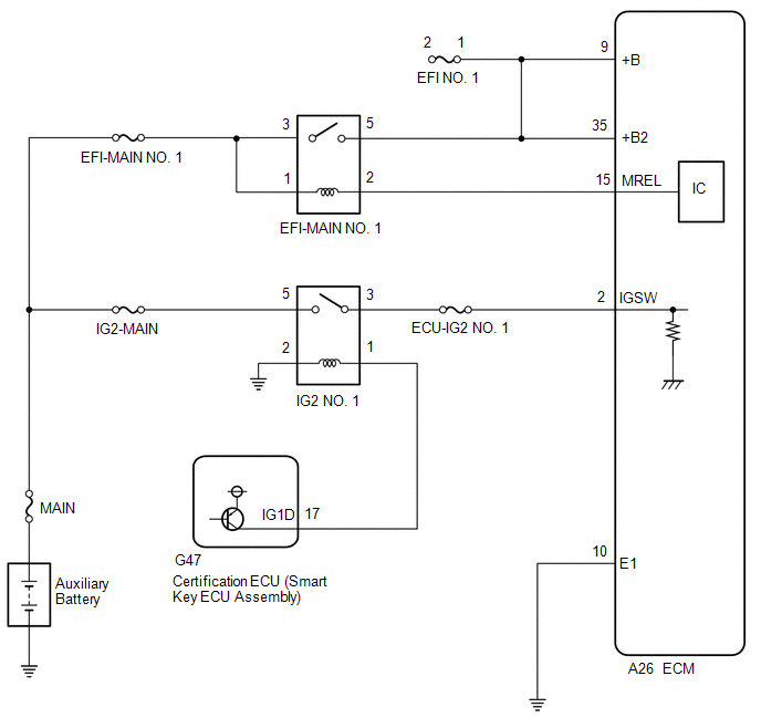
When the power switch is turned to on (IG), the auxiliary battery voltage is applied to IGSW of the ECM. When the transistor in the MREL circuit operates, current flows from the auxiliary battery to ground through the drive circuit of the EFI-MAIN NO. 1 relay, thus operating the relay which supplies power to the +B and +B2 terminals of the ECM.
WIRING DIAGRAM
CAUTION / NOTICE / HINT
NOTICE:
Inspect the fuses for circuits related to this system before performing the following procedure.
PROCEDURE
| 1. | CHECK HARNESS AND CONNECTOR (ECM - BODY GROUND) |
(a) Disconnect the ECM connector.
(b) Measure the resistance according to the value(s) in the table below.
Standard Resistance:
| Tester Connection | Condition | Specified Condition |
|---|---|---|
| A26-10 (E1) - Body ground | Always | Below 1 Ω |
| NG | .gif) | REPAIR OR REPLACE HARNESS OR CONNECTOR |
|
.gif)
| 2. | CHECK TERMINAL VOLTAGE (IGSW TERMINAL VOLTAGE) |
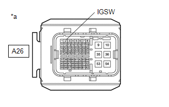
| *a | Front view of wire harness connector (to ECM) |
(a) Disconnect the ECM connector.
(b) Turn the power switch on (IG).
(c) Measure the voltage according to the value(s) in the table below.
Standard Voltage:
| Tester Connection | Condition | Specified Condition |
|---|---|---|
| A26-2 (IGSW) - Body ground | Power switch on (IG) | 11 to 14 V |
| NG | | GO TO STEP 6 |
|
| 3. | INSPECT EFI-MAIN NO. 1 RELAY |
(a) Inspect the EFI-MAIN NO. 1 relay.
Click here .gif)
| NG | | REPLACE EFI-MAIN NO. 1 RELAY |
|
| 4. | CHECK HARNESS AND CONNECTOR (EFI-MAIN NO. 1 RELAY - ECM) |
(a) Remove the EFI-MAIN NO. 1 relay from the No. 1 engine room relay block and No. 1 junction block assembly.
(b) Remove the VVT, EFI-MAIN NO. 2 and A/F HTR relays from the No. 1 engine room relay block and No. 1 junction block assembly.
HINT:
Remove the VVT, EFI-MAIN NO. 2 and A/F HTR relays connected between the checked terminals as the coil inside the relay influences the measurement value.
(c) Disconnect the ECM connector.
(d) Measure the resistance according to the value(s) in the table below.
Standard Resistance:
| Tester Connection | Condition | Specified Condition |
|---|---|---|
| 2 (EFI-MAIN NO. 1 relay) - A26-15 (MREL) | Always | Below 1 Ω |
| 5 (EFI-MAIN NO. 1 relay) - A26-9 (+B) | Always | Below 1 Ω |
| 5 (EFI-MAIN NO. 1 relay) - A26-35 (+B2) | Always | Below 1 Ω |
| 2 (EFI-MAIN NO. 1 relay) or A26-15 (MREL) - Body ground and other terminals | Always | 10 kΩ or higher |
| 5 (EFI-MAIN NO. 1 relay), A26-9 (+B) or A26-35 (+B2) - Body ground and other terminals | Always | 10 kΩ or higher |
| NG | | REPAIR OR REPLACE HARNESS OR CONNECTOR |
|
| 5. | CHECK TERMINAL VOLTAGE (POWER SOURCE OF EFI-MAIN NO. 1 RELAY) |
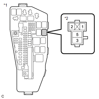
| *1 | No. 1 Engine Room Relay Block and No. 1 Junction Block Assembly |
| *2 | EFI-MAIN NO. 1 Relay |
(a) Remove the EFI-MAIN NO. 1 relay from the No. 1 engine room relay block and No. 1 junction block assembly.
(b) Measure the voltage according to the value(s) in the table below.
Standard Voltage:
| Tester Connection | Condition | Specified Condition |
|---|---|---|
| 3 (EFI-MAIN NO. 1 relay) - Body ground | Always | 11 to 14 V |
| 1 (EFI-MAIN NO. 1 relay) - Body ground | Always | 11 to 14 V |
| OK | | PROCEED TO NEXT SUSPECTED AREA SHOWN IN PROBLEM SYMPTOMS TABLE |
| NG | | REPAIR OR REPLACE HARNESS OR CONNECTOR (AUXILIARY BATTERY - EFI-MAIN NO. 1 RELAY) |
| 6. | INSPECT IG2 NO. 1 RELAY |
(a) Inspect the IG2 NO. 1 relay.
Click here
| NG | | REPLACE IG2 NO. 1 RELAY |
|
| 7. | CHECK HARNESS AND CONNECTOR (IG2 NO. 1 RELAY - ECM) |
(a) Remove the IG2 NO. 1 relay from the No. 1 engine room relay block and No. 1 junction block assembly.
(b) Disconnect the ECM connector.
(c) Measure the resistance according to the value(s) in the table below.
Standard Resistance:
| Tester Connection | Condition | Specified Condition |
|---|---|---|
| 3 (IG2 NO. 1 relay) - A26-2 (IGSW) | Always | Below 1 Ω |
| 3 (IG2 NO. 1 relay) or A26-2 (IGSW) - Body ground and other terminals | Always | 10 kΩ or higher |
| NG | | REPAIR OR REPLACE HARNESS OR CONNECTOR |
|
| 8. | CHECK TERMINAL VOLTAGE (POWER SOURCE OF IG2 NO. 1 RELAY) |
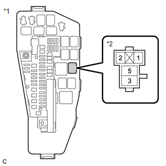
| *1 | No. 1 Engine Room Relay Block and No. 1 Junction Block Assembly |
| *2 | IG2 NO. 1 Relay |
(a) Remove the IG2 NO. 1 relay from the No. 1 engine room relay block and No. 1 junction block assembly.
(b) Measure the voltage according to the value(s) in the table below.
Standard Voltage:
| Tester Connection | Condition | Specified Condition |
|---|---|---|
| 5 (IG2 NO. 1 relay) - Body ground | Always | 11 to 14 V |
| NG | | REPAIR OR REPLACE HARNESS OR CONNECTOR (AUXILIARY BATTERY - IG2 NO. 1 RELAY) |
|
| 9. | CHECK HARNESS AND CONNECTOR (IG2 NO. 1 RELAY - BODY GROUND) |
(a) Remove the IG2 NO. 1 relay from the No. 1 engine room relay block and No. 1 junction block assembly.
(b) Measure the resistance according to the value(s) in the table below.
Standard Resistance:
| Tester Connection | Condition | Specified Condition |
|---|---|---|
| 2 (IG2 NO. 1 relay) - Body ground | Always | Below 1 Ω |
| NG | | REPAIR OR REPLACE HARNESS OR CONNECTOR |
|
| 10. | CHECK HARNESS AND CONNECTOR (CERTIFICATION ECU (SMART KEY ECU ASSEMBLY) - IG2 NO. 1 RELAY) |
(a) Disconnect the certification ECU (smart key ECU assembly) connector.
(b) Remove the IG2 NO. 1 relay from the No. 1 engine room relay block and No. 1 junction block assembly.
(c) Measure the resistance according to the value(s) in the table below.
Standard Resistance:
| Tester Connection | Condition | Specified Condition |
|---|---|---|
| G47-17 (IG1D) - 1 (IG2 NO. 1 relay) | Always | Below 1 Ω |
| G47-17 (IG1D) or 1 (IG2 NO. 1 relay) - Body ground and other terminals | Always | 10 kΩ or higher |
| OK | | GO TO SMART ACCESS SYSTEM WITH PUSH-BUTTON START |
| NG | | REPAIR OR REPLACE HARNESS OR CONNECTOR |
READ NEXT:
 VC Output Circuit
DESCRIPTION The ECM constantly generates a 5 V power source voltage from the auxiliary battery voltage supplied to the +B, +B2 (BATT) terminals to operate the microprocessor. The ECM also provides thi
MIL Circuit
DESCRIPTION The Malfunction Indicator Lamp (MIL) is used to indicate vehicle malfunctions detected by the ECM. The MIL operation can be checked visually. When the power switch is first turned to on (I
Ignition Circuit
DESCRIPTION A direct ignition system is used on this vehicle. The direct ignition system is a 1 cylinder ignition system which ignites one cylinder with one ignition coil. In the 1 cylinder ignition s
SEE MORE:
Precaution
PRECAUTION PRECAUTION FOR DISCONNECTING CABLE FROM NEGATIVE BATTERY TERMINAL NOTICE: When disconnecting the cable from the negative (-) battery terminal, initialize the following system(s) after the cable is reconnected. System Procedure Lane Control System (for Gasoline Model) P
Components
COMPONENTS ILLUSTRATION *A for Driver Side *B for Front Passenger Side *1 COURTESY LIGHT ASSEMBLY *2 FRONT DOOR TRIM BOARD SUB-ASSEMBLY *3 MULTIPLEX NETWORK MASTER SWITCH ASSEMBLY WITH FRONT DOOR UPPER ARMREST BASE PANEL *4 NO. 2 DOOR TRIM PAD *5 POWER WINDOW REGU
