Lexus ES: Inspection
INSPECTION
PROCEDURE
1. INSPECT TURN SIGNAL SWITCH
| (a) Measure the resistance according to the value(s) in the table below. Standard Resistance: Light Control Switch | Tester Connection | Condition | Specified Condition | |
*1: w/ Light Control Switch DRL OFF Position
| | 2 (L_OFF) - 12 (EL) | Light control switch in DRL OFF position*1 | Below 1 Ω | | 10 (A) - 12 (EL) | Light control switch in AUTO position | Below 1 Ω | | 14 (T) - 12 (EL) | Light control switch in tail position | Below 1 Ω | | 5 (H) - 12 (EL) | Light control switch in head position | Below 1 Ω | Dimmer Passing Switch | Tester Connection | Condition | Specified Condition | | 6 (HF) - 12 (EL) | Dimmer switch in high flash position | Below 1 Ω | | 1 (HU) - 12 (EL) | Dimmer switch in high position | Below 1 Ω | Turn Signal Switch | Tester Connection | Condition | Specified Condition | | 9 (TR) - 12 (EL) | Turn signal switch in neutral position | 10 kΩ or higher | | 3 (TL) - 12 (EL) | Turn signal switch in neutral position | 10 kΩ or higher | | 9 (TR) - 12 (EL) | Turn signal switch in right turn position | Below 1 Ω | | 9 (TR) - 12 (EL) | Turn signal switch in full right turn position | Below 1 Ω | | 9 (TR) - 11 (CR) | Turn signal switch in full right turn position | Below 1 Ω | | 11 (CR) - 12 (EL) | Turn signal switch in full right turn position | Below 1 Ω | | 3 (TL) - 12 (EL) | Turn signal switch in left turn position | Below 1 Ω | | 3 (TL) - 12 (EL) | Turn signal switch in full left turn position | Below 1 Ω | | 3 (TL) - 11 (CR) | Turn signal switch in full left turn position | Below 1 Ω | | 11 (CR) - 12 (EL) | Turn signal switch in full left turn position | Below 1 Ω | Automatic High Beam Switch | Tester Connection | Condition | Specified Condition | | 16 (AHB) - 12 (EL) | Automatic high beam switch off | 10 kΩ or higher | | Automatic high beam switch on | Below 1 Ω | If the result is not as specified, replace the turn signal switch. HINT: -
The left turn or right turn condition indicates a condition in which the turn signal switch will return to the neutral position after releasing your hand from the turn signal switch (turn signal switch is operated approximately 6.3°).
-
The full left turn or full right turn condition indicates a condition in which the turn signal switch will not return to the neutral position after releasing your hand from the turn signal switch (turn signal switch is operated 10.5°).
| 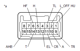 | | *a | Component without harness connected (Turn Signal Switch) | | |
| (b) Apply auxiliary battery voltage to the turn signal switch and check that the light illuminates. OK: | Measurement Condition | Condition | Specified Condition | | Auxiliary battery positive (+) → 15 (BLED) Auxiliary battery negative (-) → 7 (ELED) | Always | Switch indicator illuminates | If the result is not as specified, replace the turn signal switch. | 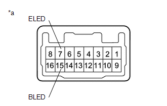 | | *a | Component without harness connected (Turn Signal Switch) | | |
READ NEXT:
INSTALLATION PROCEDURE 1. INSTALL TURN SIGNAL SWITCH (a) Engage the claw as shown in the illustration. Install in this Direction (b) Install the turn signal switch with the 2 screws. 2. INST
COMPONENTS ILLUSTRATION *1 HEADLIGHT ECU SUB-ASSEMBLY *2 HEADLIGHT GASKET ● Non-reusable part - -
SEE MORE:
REMOVAL CAUTION / NOTICE / HINT The necessary procedures (adjustment, calibration, initialization, or registration) that must be performed after parts are removed and installed, or replaced during parking assist ECU removal/installation are shown below. Necessary Procedure After Parts Removed/Instal
DESCRIPTION This procedure is for troubleshooting when the brake warning light / red (malfunction) remains on but no DTCs are output. The skid control ECU (brake actuator assembly) controls the brake warning light / red (malfunction) in the combination meter assembly via CAN communication. WIRING DI
© 2016-2026 Copyright www.lexguide.net

 Installation