Lexus ES: Installation
Lexus ES (XZ10) Service Manual / Vehicle Interior / Lighting (ext) / Headlight Dimmer Switch / Installation
INSTALLATION
PROCEDURE
1. INSTALL TURN SIGNAL SWITCH
(a) Engage the claw as shown in the illustration.
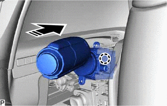
.png) | Install in this Direction |
(b) Install the turn signal switch with the 2 screws.
2. INSTALL UPPER STEERING COLUMN COVER
Click here .gif)
3. INSTALL LOWER STEERING COLUMN COVER SUB-ASSEMBLY
Click here
4. CUSTOMIZE POWER TILT AND POWER TELESCOPIC STEERING COLUMN SYSTEM (for Power Tilt and Power Telescopic Steering Column)
Click here
READ NEXT:
 Components
COMPONENTS ILLUSTRATION *1 HEADLIGHT ECU SUB-ASSEMBLY *2 HEADLIGHT GASKET ● Non-reusable part - -
Removal
REMOVAL CAUTION / NOTICE / HINT The necessary procedures (adjustment, calibration, initialization or registration) that must be performed after parts are removed and installed, or replaced during head
SEE MORE:
Adjustment
ADJUSTMENT CAUTION / NOTICE / HINT *a Centering Bolt *b Standard Bolt HINT:
Centering bolts are used to mount the door hinge to the door. The door cannot be adjusted with the centering bolts installed. Substitute the centering bolts with standard bolts when making adjustments.
Sp
DC/DC Converter Temperature Sensor 2 Circuit Short to Ground (P0E5811,P0E5815)
DESCRIPTION The motor generator control ECU (MG ECU), which is built into in the inverter with converter assembly, detects the temperature of the boost converter using the boost converter temperature sensor 2 (lower). The motor generator control ECU (MG ECU) also detects malfunctions in the boost co
© 2016-2026 Copyright www.lexguide.net
