Lexus ES: Inspection
INSPECTION
PROCEDURE
1. INSPECT OUTER MIRROR SWITCH ASSEMBLY (w/o Memory)
(a) Check the mirror select switch and mirror surface adjust switch.
| (1) Select the mirror select switch to the L position. |
|
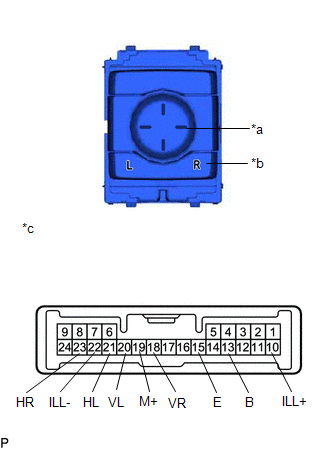
(2) Measure the resistance according to the value(s) in the table below.
Standard Resistance (for left side):
| Tester Connection | Condition | Specified Condition |
|---|---|---|
| 20 (VL) - 13 (B) 19 (M+) - 15 (E) | Up | Below 1 Ω |
| Off | 10 kΩ or higher | |
| 20 (VL) - 15 (E) 19 (M+) - 13 (B) | Down | Below 1 Ω |
| Off | 10 kΩ or higher | |
| 21 (HL) - 13 (B) 19 (M+) - 15 (E) | Left | Below 1 Ω |
| Off | 10 kΩ or higher | |
| 21 (HL) - 15 (E) 19 (M+) - 13 (B) | Right | Below 1 Ω |
| Off | 10 kΩ or higher |
(3) Select the mirror select switch to the R position.
(4) Measure the resistance according to the value(s) in the table below.
Standard Resistance (for right side):
| Tester Connection | Condition | Specified Condition |
|---|---|---|
| 18 (VR) - 13 (B) 19 (M+) - 15 (E) | Up | Below 1 Ω |
| Off | 10 kΩ or higher | |
| 18 (VR) - 15 (E) 19 (M+) - 13 (B) | Down | Below 1 Ω |
| Off | 10 kΩ or higher | |
| 23 (HR) - 13 (B) 19 (M+) - 15 (E) | Left | Below 1 Ω |
| Off | 10 kΩ or higher | |
| 23 (HR) - 15 (E) 19 (M+) - 13 (B) | Right | Below 1 Ω |
| Off | 10 kΩ or higher |
If the result is not as specified, replace the outer mirror switch assembly.
(b) Check the switch illumination.
(1) Apply auxiliary battery voltage between the terminals of the light and check the operation of the light.
OK:
| Measurement Condition | Specified Condition |
|---|---|
| Auxiliary battery positive (+) → Terminal 10 (ILL+) Auxiliary battery negative (-) → Terminal 22 (ILL-) | Light comes on |
If the result is not as specified, replace the outer mirror switch assembly.
2. INSPECT OUTER MIRROR SWITCH ASSEMBLY (w/ Memory)
| (a) Check the mirror select switch. (w/o Automatic Retractable Mirror) (1) Measure the resistance according to the value(s) in the table below. Standard Resistance:
If the result is not as specified, replace the outer mirror switch assembly. |
|
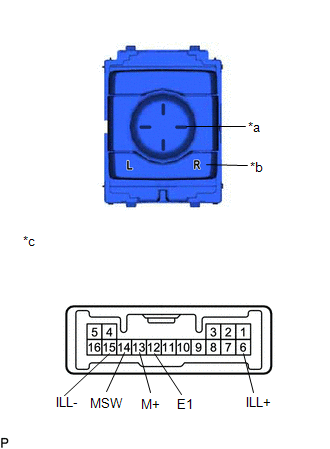
(b) Check the mirror surface adjust switch. (w/o Automatic Retractable Mirror)
(1) Select the mirror select switch to the L position or R position.
(2) Measure the resistance according to the value(s) in the table below.
Standard Resistance:
| Tester Connection | Condition | Specified Condition |
|---|---|---|
| 12 (E1) - 13 (M+) | Mirror surface adjust switch pressed up | 90 to 110Ω |
| Off | 10 kΩ or higher | |
| Mirror surface adjust switch pressed down | 437 to 503Ω | |
| Off | 10 kΩ or higher | |
| Mirror surface adjust switch pressed left | 744 to 856Ω | |
| Off | 10 kΩ or higher | |
| Mirror surface adjust switch pressed right | 225 to 275Ω | |
| Off | 10 kΩ or higher |
If the result is not as specified, replace the outer mirror switch assembly.
(c) Check the switch illumination. (w/o Automatic Retractable Mirror)
(1) Apply auxiliary battery voltage between the terminals of the light and check the operation of the light.
OK:
| Measurement Condition | Specified Condition |
|---|---|
| Auxiliary battery positive (+) → Terminal 6 (ILL+) Auxiliary battery negative (-) → Terminal 15 (ILL-) | Light comes on |
If the result is not as specified, replace the outer mirror switch assembly.
| (d) Check the mirror retract switch. (w/ Automatic Retractable Mirror) (1) Measure the resistance according to the value(s) in the table below. Standard Resistance:
If the result is not as specified, replace the outer mirror switch assembly. |
|
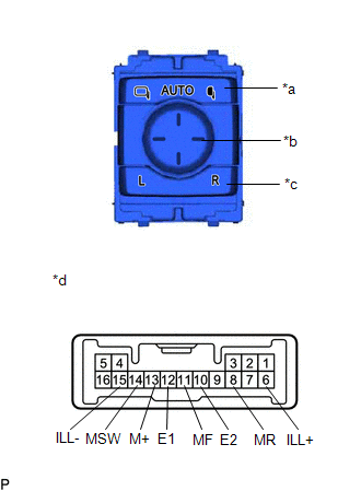
(e) Check the mirror select switch. (w/ Automatic Retractable Mirror)
(1) Measure the resistance according to the value(s) in the table below.
Standard Resistance:
| Tester Connection | Condition | Specified Condition |
|---|---|---|
| 12 (E1) - 14 (MSW) | R | Below 10 Ω |
| L | 90 to 110 Ω | |
| Off | 10 kΩ or higher |
(f) Check the mirror surface adjust switch. (w/ Automatic Retractable Mirror)
(1) Select the mirror select switch to the L position or R position.
(2) Measure the resistance according to the value(s) in the table below.
Standard Resistance:
| Tester Connection | Condition | Specified Condition |
|---|---|---|
| 12 (E1) - 13 (M+) | Mirror surface adjust switch pressed up | 90 to 110 Ω |
| Off | 10 kΩ or higher | |
| Mirror surface adjust switch pressed down | 437 to 503 Ω | |
| Off | 10 kΩ or higher | |
| Mirror surface adjust switch pressed left | 744 to 856 Ω | |
| Off | 10 kΩ or higher | |
| Mirror surface adjust switch pressed right | 225 to 275 Ω | |
| Off | 10 kΩ or higher |
(g) Check the switch illumination. (w/ Automatic Retractable Mirror)
(1) Apply auxiliary battery voltage between the terminals of the light and check the operation of the light.
OK:
| Measurement Condition | Specified Condition |
|---|---|
| Auxiliary battery positive (+) → Terminal 6 (ILL+) Auxiliary battery negative (-) → Terminal 15 (ILL-) | Light comes on |
If the result is not as specified, replace the outer mirror switch assembly.
READ NEXT:
 Installation
INSTALLATION PROCEDURE 1. INSTALL OUTER MIRROR SWITCH ASSEMBLY (a) Engage the 4 claws to install the outer mirror switch assembly. 2. INSTALL MULTIPLEX NETWORK MASTER SWITCH ASSEMBLY WI
Components
COMPONENTS ILLUSTRATION *A for Driver Side *B for Front Passenger Side *1 COURTESY LIGHT ASSEMBLY *2 FRONT DOOR TRIM BOARD SUB-ASSEMBLY *3 MULTIPLEX NETWORK MASTER SWITCH ASS
SEE MORE:
Open in One Side of Bus 2 Branch Line
DESCRIPTION When the CAN bus main lines are normal (no open, short to ground, short to +B or short between lines) and there is an ECU or sensor on the "Communication Bus Check" screen that is indicated as not communicating or whose connection status on the "Communication Bus Check" screen changes in
On-vehicle Inspection
ON-VEHICLE INSPECTION PROCEDURE 1. INSPECT FRONT LOWER BALL JOINT ASSEMBLY (a) Check for looseness. (1) Lift up the vehicle. (2) Move the front lower No. 1 suspension arm sub-assembly up and down by hand with a force of 294 N (30 kgf) or more to check that there is no looseness at the front lower
