Lexus ES: Components
COMPONENTS
ILLUSTRATION
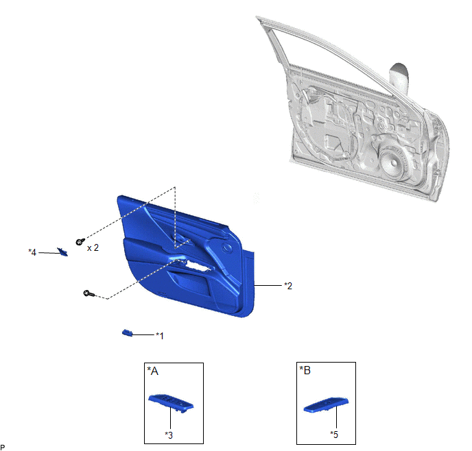
| *A | for Driver Side | *B | for Front Passenger Side |
| *1 | COURTESY LIGHT ASSEMBLY | *2 | FRONT DOOR TRIM BOARD SUB-ASSEMBLY |
| *3 | MULTIPLEX NETWORK MASTER SWITCH ASSEMBLY WITH FRONT DOOR UPPER ARMREST BASE PANEL | *4 | NO. 2 DOOR TRIM PAD |
| *5 | POWER WINDOW REGULATOR SWITCH ASSEMBLY WITH FRONT DOOR UPPER ARMREST BASE PANEL | - | - |
ILLUSTRATION
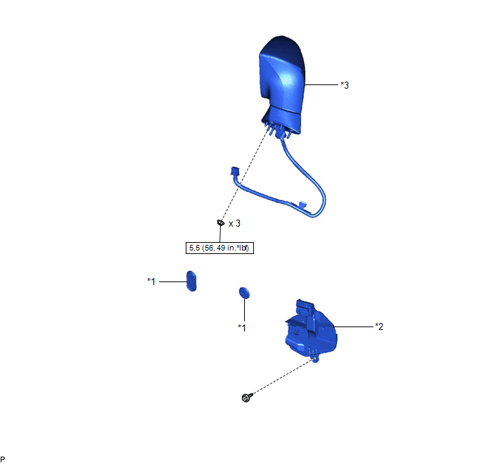
| *1 | HOLE PLUG | *2 | OUTER MIRROR INSTALL HOLE COVER |
| *3 | OUTER REAR VIEW MIRROR ASSEMBLY | - | - |
.png) | N*m (kgf*cm, ft.*lbf): Specified torque | - | - |
ILLUSTRATION
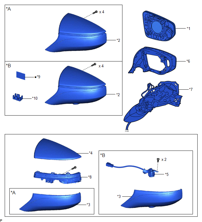
| *A | w/o Panoramic View Monitor System | *B | w/ Panoramic View Monitor System |
| *1 | OUTER MIRROR | *2 | OUTER MIRROR COVER ASSEMBLY |
| *3 | OUTER MIRROR LOWER COVER | *4 | OUTER MIRROR UPPER COVER |
| *5 | SIDE TELEVISION CAMERA ASSEMBLY | *6 | VISOR COVER ASSEMBLY |
| *7 | OUTER MIRROR RETRACTOR | *8 | SIDE TURN SIGNAL LIGHT ASSEMBLY |
| *9 | OUTER MIRROR TAPE | *10 | CAMERA CONNECTOR CLAMP |
| ● | Non-reusable part | - | - |
READ NEXT:
 Removal
REMOVAL CAUTION / NOTICE / HINT The necessary procedures (adjustment, calibration, initialization, or registration) that must be performed after parts are removed and installed, or replaced during out
Disassembly
DISASSEMBLY CAUTION / NOTICE / HINT HINT:
Use the same procedure for the RH side and LH side.
The following procedure is for the LH side.
PROCEDURE 1. REMOVE OUTER MIRROR Click here 2. REMO
Inspection
INSPECTION PROCEDURE 1. INSPECT OUTER REAR VIEW MIRROR ASSEMBLY RH (a) Check the operation of the mirror surface. NOTICE: If the mirror surface is fully turned to the right, left, upward or downward p
SEE MORE:
Installation
INSTALLATION PROCEDURE 1. INSTALL WATER INLET WITH THERMOSTAT SUB-ASSEMBLY (a) Install a new gasket to the water inlet with thermostat sub-assembly. (b) Install the water inlet with thermostat sub-assembly with the 2 bolts and 2 nuts. Torque: 10 N·m {102 kgf·cm, 7 ft·lbf} 2. CONNECT WATER BY-PAS
Intake Air Temperature Sensor 1 Bank 1 Circuit Short to Battery or Open (P011015)
DESCRIPTION Refer to DTC P011011. Click here HINT: When DTC P011015 is stored, the ECM enters fail-safe mode. During fail-safe mode, the intake air temperature is estimated to be 20°C (68°F) by the ECM. Fail-safe mode continues until a pass condition is detected, and the engine switch is then tu
