Lexus ES: When Auxiliary Battery Is Discharged
WHEN AUXILIARY BATTERY IS DISCHARGED
WHEN AUXILIARY BATTERY IS DISCHARGED
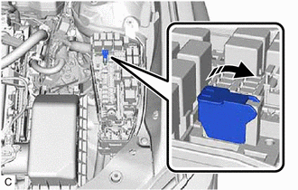
(a) When the auxiliary battery is discharged.
NOTICE:
The booster terminal can only be used to rescue this vehicle and can not be used to rescue another vehicle with a discharged battery.
HINT:
The following problems indicate that the auxiliary battery is discharged:
- No display appears on the instrument panel when the power switch is turned on (IG).
- The hybrid system does not start.
- The headlights are dim.
- The sound from the horn is weak.
(1) Engage the parking brake.
(2) Turn the power switch off and remove the key from the interior detection area.
(3) Remove the engine room relay block and junction block assembly cover.
(4) Open the booster terminal cover.
(5) Using booster cables, connect the 12 V auxiliary battery of the rescue vehicle to the auxiliary battery of the stalled vehicle as shown in the illustration.
| Connecting Sequence | Connecting Location |
|---|---|
| 1 | Booster terminal of stalled vehicle |
| 2 | Positive (+) auxiliary battery terminal of rescue vehicle |
| 3 | Negative (-) auxiliary battery terminal of rescue vehicle |
| 4 | Position shown in the illustration on stalled vehicle |
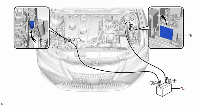
| *a | Booster Terminal | *b | Auxiliary Battery of Rescue Vehicle |
(6) Start the engine of the rescue vehicle and run the engine at a speed slightly higher than usual.
(7) Turn the power switch on (READY).
NOTICE:
Immediately disconnect the booster cables in the reverse order of connection after the hybrid system has started. Do not leave the booster cables connected because they are not designed for recharging purposes.
HINT:
If the hybrid system fails to start and "Traction Battery Needs to be Protected Refrain From the Use of N Position" or "Traction Battery Needs to be Protected Shift into P to Restart" is displayed on the multi-information display, the HV battery may be discharged.
READ NEXT:
 Removal
REMOVAL CAUTION / NOTICE / HINT The necessary procedures (adjustment, calibration, initialization or registration) that must be performed after parts are removed and installed, or replaced during auxi
Components
COMPONENTS ILLUSTRATION *1 AUXILIARY BATTERY *2 BATTERY HOSE *3 NEGATIVE AUXILIARY BATTERY TERMINAL *4 POSITIVE AUXILIARY BATTERY TERMINAL *5 NO. 3 BATTERY CLAMP *6 TERMI
SEE MORE:
System Diagram
SYSTEM DIAGRAM Communication Table Transmitter Receiver Signal Communication Method Rear Window Defogger Switch (Air Conditioning Control Assembly) Air Conditioning Amplifier Assembly Rear Window Defogger Switch Signal LIN
Noise Occurs
PROCEDURE 1. CHECK NOISE CONDITION (a) Check from which direction the noise comes (front left or right, or rear left or right). OK: The location of the noise source can be determined. NG GO TO STEP 3
OK 2. CHECK SPEAKERS (a) Check the installation condi
