Lexus ES: Inspection
INSPECTION
PROCEDURE
1. INSPECT STARTER ASSEMBLY
CAUTION:
As a large electric current passes through the cable during this inspection, a thick cable must be used. If not, the cable may become hot and cause injury.
NOTICE:
Perform each of the following tests within 3 to 5 seconds to prevent the coil from burning out.
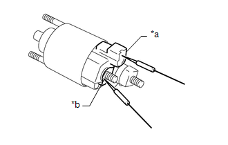
(a) Perform a pull-in test.
(1) Remove the nut, and disconnect the field coil lead wire from terminal C.
(2) Connect a battery to the magnet starter switch assembly as shown in the illustration. Check that the clutch pinion gear moves outward.
If the clutch pinion gear does not move outward, replace the magnet starter switch assembly.
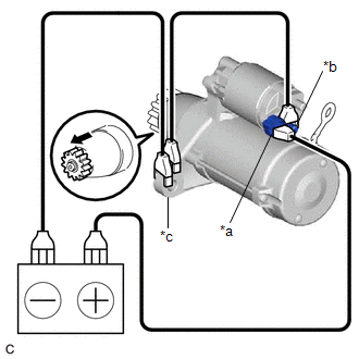
| *a | Terminal 50 |
| *b | Terminal C |
| *c | Starter Body |
.png) | Moves outward |
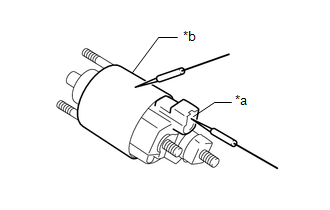
(b) Perform a holding test.
(1) While maintaining the battery connections of the pull-in test, disconnect the negative (-) lead from terminal C. Check that the clutch pinion gear does not return inward.
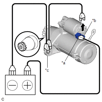
| *a | Terminal 50 |
| *b | Terminal C |
| *c | Starter Body |
| | Disconnect |
If the clutch pinion gear returns inward, replace the magnet starter switch assembly.
(c) Perform a return test.
(1) Disconnect the negative (-) lead from the starter body. Check that the clutch pinion gear returns inward.
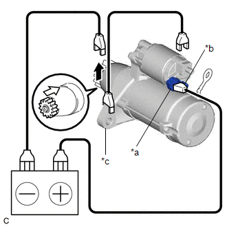
| *a | Terminal 50 |
| *b | Terminal C |
| *c | Starter Body |
| | Disconnect |
.png) | Returns inward |
If the clutch pinion gear does not return inward, replace the magnet starter switch assembly.
(d) Perform a no-load performance test.
(1) Connect the field coil lead wire to terminal C with the nut. Make sure that the field coil lead wire is not grounded.
Torque:
10 N·m {102 kgf·cm, 7 ft·lbf}
(2) Secure the starter assembly in a vise between aluminum plates.
NOTICE:
Ensure that the starter assembly is secured in the vise to prevent it from falling out.
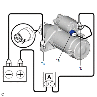
| *a | Terminal 50 |
| *b | Terminal 30 |
| *c | Starter Body |
| | Rotates |
(3) Connect the battery and an ammeter to the starter assembly as shown in the illustration.
NOTICE:
Do not allow any lead to get caught as the clutch pinion gear operates.
(4) Check that the starter assembly operates smoothly and steadily while the clutch pinion gear is moving outward.
Measure the current according to the value(s) in the table below.
Standard Current:
| Tester Connection | Condition | Specified Condition |
|---|---|---|
| Battery positive (+) terminal - Terminal 30 - Terminal 50 | 11.5 V | Below 90 A |
If the result is not as specified, replace the starter assembly.
2. INSPECT STARTER ARMATURE ASSEMBLY
HINT:
If there is no continuity between any segments, replace the starter armature assembly.
(a) Check the commutator appearance.
If the surface is dirty or burnt, restore it with sandpaper (400-grit) or on a lathe.
| (b) Check the commutator for an open circuit. (1) Measure the resistance according to the value(s) in the table below. Standard Resistance:
If the result is not as specified, replace the starter armature assembly. |
|
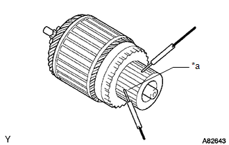
| (c) Check the commutator for a short circuit. (1) Measure the resistance according to the value(s) in the table below. Standard Resistance:
If the result is not as specified, replace the starter armature assembly. |
|
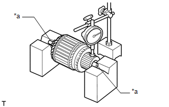
| (d) Check the commutator for runout. (1) Place the armature shaft on V-blocks. (2) Using a dial indicator, measure the runout. Maximum Runout: 0.05 mm (0.00197 in.) If the runout is greater than the maximum, replace the starter armature assembly. |
|
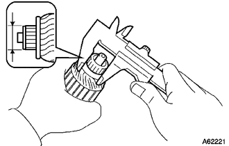
| (e) Using a vernier caliper, measure the commutator diameter. Standard Diameter: 29 mm (1.14 in.) Minimum Diameter: 28 mm (1.10 in.) If the diameter is less than the minimum, replace the starter armature assembly. |
|
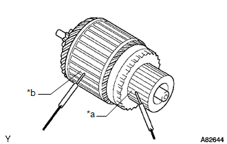
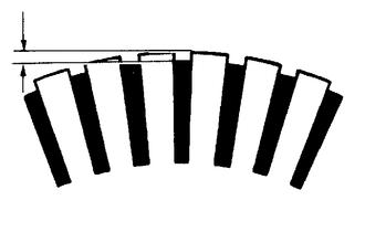
| (f) Check that the undercut portion between the segments is free of foreign matter and measure its depth. Standard Undercut Depth: 0.7 mm (0.0276 in.) Minimum Undercut Depth: 0.2 mm (0.00787 in.) If the undercut depth is less than the minimum, replace the starter assembly. |
|
3. INSPECT STARTER BRUSH HOLDER ASSEMBLY
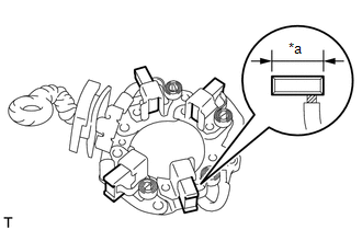
(a) Check the brush length.
| (1) Using a vernier caliper, measure the brush length. Standard Length: 14.4 mm (0.567 in.) Minimum Length: 9.0 mm (0.354 in.) If the brush length is less than the minimum, replace the starter brush holder assembly. |
|
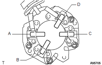
| (b) Check the brush holder resistance. (1) Measure the resistance according to the value(s) in the table below. Standard Resistance:
If the result is not as specified, replace the starter brush holder assembly. |
|
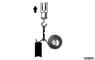
(c) Check the brush spring load.
| (1) Take a pull scale reading the instant the brush spring separates from the brush. Standard Spring Load: 22.3 to 27.3 N (2.27 to 2.78 kgf, 5.01 to 6.14 lbf) Minimum Spring Load: 13.8 N (1.41 kgf, 3.1 lbf) If the spring load is less than the minimum, replace the starter brush holder assembly. |
|
4. INSPECT STARTER CLUTCH
| | Lock |
| | Free |
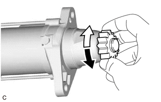
(a) Check the clutch pinion gear.
(1) Rotate the clutch pinion gear counterclockwise and check that it turns freely. Try to rotate the clutch pinion gear clockwise and check that it locks.
If the clutch pinion gear does not operate as specified, replace the repair service starter kit.
5. INSPECT MAGNET STARTER SWITCH ASSEMBLY
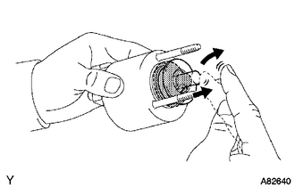
| (a) Check the plunger. (1) Push in the plunger and check that it returns quickly to its original position. If the plunger does not operate as specified, replace the magnet starter switch assembly. |
|
| (b) Check the pull-in coil for an open circuit. (1) Measure the resistance according to the value(s) in the table below. Standard Resistance:
If the result is not as specified, replace the magnet starter switch assembly. |
|
| (c) Check the holding coil for an open circuit. (1) Measure the resistance according to the value(s) in the table below. Standard Resistance:
If the result is not as specified, replace the magnet starter switch assembly. |
|
READ NEXT:
 Reassembly
REASSEMBLY PROCEDURE 1. INSTALL PLANETARY GEAR (a) Apply high-temperature grease to the 3 planetary gears, 3 planetary gear shafts and repair service starter kit. High-temperature Grease (b)
Installation
INSTALLATION PROCEDURE 1. INSTALL STARTER ASSEMBLY (a) Install the starter assembly with the 2 bolts. Torque: 46 N·m {469 kgf·cm, 34 ft·lbf} (b) Connect the engine wire to the terminal 30 with the
Starting System
Parts LocationPARTS LOCATION ILLUSTRATION *1 STARTER ASSEMBLY *2 ECM *3 ENGINE ROOM RELAY BLOCK AND JUNCTION BLOCK ASSEMBLY - ST RELAY - FL MAIN FUSE - ST FUSE *4 PARK/NEUTRAL POS
SEE MORE:
Hybrid/EV Battery Cooling Fan 1 Component Internal Failure (P0A8196)
DESCRIPTION Refer to the description for DTC P0A8111. Click here DTC No. Detection Item DTC Detection Condition Trouble Area MIL Warning Indicate P0A8196 Hybrid/EV Battery Cooling Fan 1 Component Internal Failure The battery cooling blower assembly is malfunctioning and the ac
USB Device Malfunction (B1585)
DESCRIPTION This DTC is stored when a malfunction occurs in a connected device. DTC No. Detection Item DTC Detection Condition Trouble Area B1585 USB Device Malfunction When any of the following conditions is met:
A non mass-storage class or incompatible protocol USB device is co
