Lexus ES: Reassembly
REASSEMBLY
PROCEDURE
1. INSTALL PLANETARY GEAR
(a) Apply high-temperature grease to the 3 planetary gears, 3 planetary gear shafts and repair service starter kit.
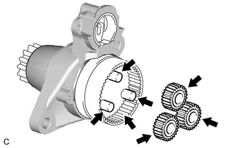
.png) | High-temperature Grease |
(b) Install the 3 planetary gears to the repair service starter kit.
2. INSTALL RUBBER SEAL
(a) Install the rubber seal to the repair service starter kit.
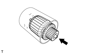
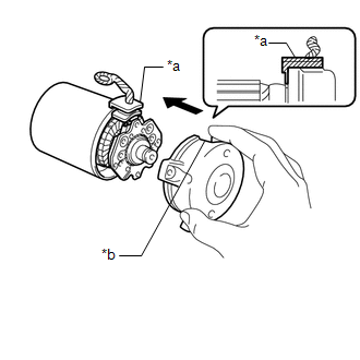
3. INSTALL STARTER ARMATURE ASSEMBLY
| (a) Install the starter armature assembly to the starter yoke assembly. NOTICE: The magnet of the starter yoke assembly may attract the starter armature assembly when the starter armature assembly is installed, causing the magnet to break. |
|
4. INSTALL STARTER BRUSH HOLDER ASSEMBLY
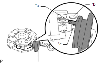
| (a) Hold the brush spring back and set the 4 brushes as shown in the illustration. |
|
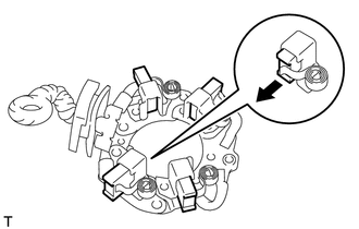
| (b) Install the starter brush holder assembly to the starter armature assembly and push in the 4 brushes as shown in the illustration. |
|
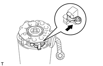
| (c) Fit the protrusion of the grommet between the negative (-) brush holder plate and positive (+) motor lead wire. |
|
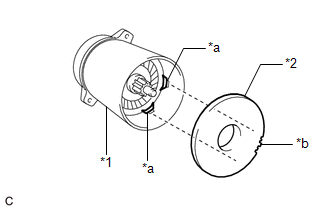
5. INSTALL STARTER COMMUTATOR END FRAME ASSEMBLY
| (a) Install the starter commutator end frame assembly to the starter yoke assembly. NOTICE: Align the field coil lead wire rubber of the starter yoke assembly with the cutout of the starter commutator end frame assembly. |
|
(b) Install the 2 screws.
Torque:
1.5 N·m {15 kgf·cm, 13 in·lbf}
6. INSTALL STARTER ARMATURE PLATE
| (a) Align the starter armature plate so that the protrusion fits between the stoppers of the starter yoke assembly, and install the starter armature plate. NOTICE: Make sure the protrusion of the starter armature plate is inserted between the stoppers of the starter yoke assembly. |
|
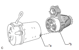
7. INSTALL STARTER YOKE ASSEMBLY
| (a) Align the protrusion of the starter yoke assembly with the cutout of the repair service starter kit. |
|
(b) Using a T25 "TORX" socket wrench, install the starter yoke assembly with the 2 through bolts.
Torque:
6.0 N·m {61 kgf·cm, 53 in·lbf}
8. INSTALL MAGNET STARTER SWITCH ASSEMBLY
(a) Apply high-temperature grease to the plunger as shown in the illustration.
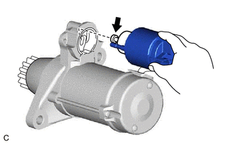
| | High-temperature Grease |
(b) Hang the hook of the magnet starter switch assembly on the pinion drive lever.
(c) Install the magnet starter switch assembly with the 2 nuts.
Torque:
7.5 N·m {76 kgf·cm, 66 in·lbf}
(d) Connect the field coil lead wire to the magnet starter switch assembly with the nut.
Torque:
10 N·m {102 kgf·cm, 7 ft·lbf}
READ NEXT:
 Installation
INSTALLATION PROCEDURE 1. INSTALL STARTER ASSEMBLY (a) Install the starter assembly with the 2 bolts. Torque: 46 N·m {469 kgf·cm, 34 ft·lbf} (b) Connect the engine wire to the terminal 30 with the
Starting System
Parts LocationPARTS LOCATION ILLUSTRATION *1 STARTER ASSEMBLY *2 ECM *3 ENGINE ROOM RELAY BLOCK AND JUNCTION BLOCK ASSEMBLY - ST RELAY - FL MAIN FUSE - ST FUSE *4 PARK/NEUTRAL POS
SEE MORE:
Automatic High Beam Switch Indicator does not Come ON
DESCRIPTION When the automatic high beam system is on, the steering sensor illuminates the automatic high beam switch indicator. WIRING DIAGRAM PROCEDURE 1. READ VALUE USING TECHSTREAM (a) Connect the Techstream to the DLC3. (b) Turn the engine switch on (IG). (c) Turn the Techstream on. (
Electric Parking Brake does not Operate
WIRING DIAGRAM CAUTION / NOTICE / HINT NOTICE:
The electric parking brake may still operate up to 20 seconds after the engine switch is turned off. Before disconnecting connectors or fuses, turn the engine switch off and wait 20 seconds or more.
Inspect the fuses for circuits related to this s
