Lexus ES: Inspection
INSPECTION
PROCEDURE
1. INSPECT FUEL PRESSURE SENSOR (FUEL DELIVERY PIPE WITH SENSOR ASSEMBLY LH)
NOTICE:
- Do not remove the fuel pressure sensor from the fuel delivery pipe with sensor assembly LH.
- If the fuel pressure sensor is removed, replace the fuel pressure sensor (fuel delivery pipe with sensor assembly LH) with a new one.
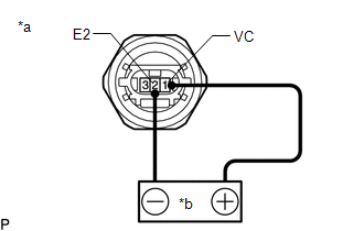
(a) Check the fuel pressure sensor (fuel delivery pipe with sensor assembly LH) output voltage.
| (1) Apply 5 V between terminals 1 (VC) and 2 (E2). NOTICE:
HINT: If a stable power supply is not available, connect 4 nickel-metal hydride batteries (1.2 V each) or equivalent in series. |
|
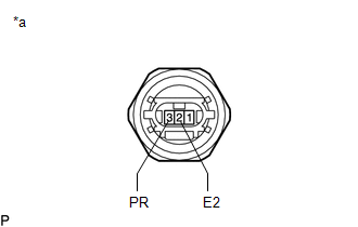
| (2) Measure the voltage according to the value(s) in the table below. Standard Voltage:
*: The output voltage changes depending on the voltage applied to the terminals. If the result is not as specified, replace the fuel pressure sensor (fuel delivery pipe with sensor assembly LH). |
|
READ NEXT:
 Installation
INSTALLATION PROCEDURE 1. INSTALL FUEL PIPE PLUG SUB-ASSEMBLY (a) Install a new O-ring, No. 1 fuel injector back-up ring, No. 2 fuel injector back-up ring and No. 3 fuel injector back-up ring to the f
Components
COMPONENTS ILLUSTRATION *1 REAR SEAT INNER BELT ASSEMBLY LH *2 REAR CENTER SEAT LAP TYPE BELT ASSEMBLY *3 WASHER *4 REAR SEAT CUSHION ASSEMBLY *5 REAR SEAT CUSHION LOCK HOOK
SEE MORE:
Removal
REMOVAL CAUTION / NOTICE / HINT The necessary procedures (adjustment, calibration, initialization, or registration) that must be performed after parts are removed and installed, or replaced during side television camera assembly removal/installation are shown below. Necessary Procedure After Parts R
Components
COMPONENTS ILLUSTRATION *1 FRONT DRIVE SHAFT OIL SEAL LH *2 FRONT DRIVE SHAFT OIL SEAL RH ● Non-reusable part - -
