Lexus ES: Components
Lexus ES (XZ10) Service Manual / Engine & Hybrid System / 2gr-fks (cooling) / Water Pump / Components
COMPONENTS
ILLUSTRATION
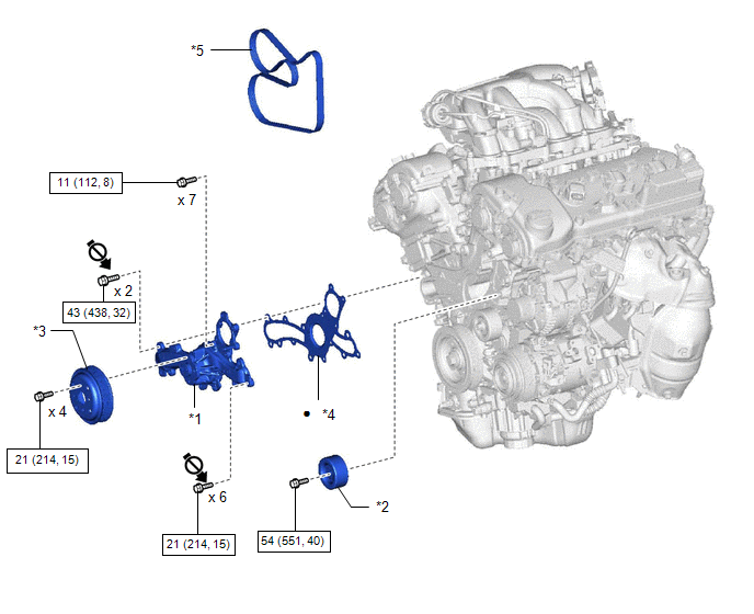
| *1 | ENGINE WATER PUMP ASSEMBLY | *2 | NO. 2 IDLER PULLEY SUB-ASSEMBLY |
| *3 | WATER PUMP PULLEY | *4 | WATER PUMP GASKET |
| *5 | V-RIBBED BELT | - | - |
.png) | N*m (kgf*cm, ft.*lbf): Specified torque | ● | Non-reusable part |
.png) | Do not apply lubricants to the threaded parts | - | - |
READ NEXT:
 On-vehicle Inspection
ON-VEHICLE INSPECTION CAUTION / NOTICE / HINT HINT:
Water Pump Construction Evaporation Port and Drain Plug: *1 Evaporation Port *2 Mechanical Seal *3 Fluid Catch Pocket *4 Drai
Removal
REMOVAL CAUTION / NOTICE / HINT The necessary procedures (adjustment, calibration, initialization or registration) that must be performed after parts are removed and installed, or replaced during engi
Installation
INSTALLATION PROCEDURE 1. INSTALL ENGINE WATER PUMP ASSEMBLY (a) Install a new water pump gasket and the engine water pump assembly with the 15 bolts. Torque: Bolt (A) : 43 N·m {438 kgf·cm, 32
SEE MORE:
Hybrid/EV Powertrain Control Module Unexpected Operation (P0A1D94)
DESCRIPTION The battery ECU assembly monitors the hybrid vehicle control ECU via CAN communication. If the battery ECU assembly detects that the hybrid vehicle control ECU is malfunctioning, it will illuminate the MIL and store a DTC. DTC No. Detection Item DTC Detection Condition Trouble A
Control Module Communication Bus Off (U0073,U0100,U0101,U0126,U0129,U0142,U0155,U0242)
DESCRIPTION These DTCs are stored if a CAN communication malfunction occurs between the headlight ECU sub-assembly LH and other ECUs. for LED Type Turn Signal Light DTC No. Detection Item DTC Detection Condition Trouble Area DTC Output from U0073 Control Module Communication Bus Off
© 2016-2026 Copyright www.lexguide.net
