Lexus ES: Inspection
INSPECTION
PROCEDURE
1. INSPECT FRONT DRIVE SHAFT ASSEMBLY
| (a) Check that there is no excessive play in the radial direction of the outboard joint. |
|
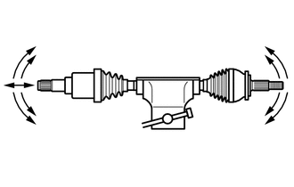
(b) Check that the inboard joint slides smoothly in the thrust direction.
(c) Check that there is no excessive play in the radial direction of the inboard joint.
(d) Check the boots for damage.
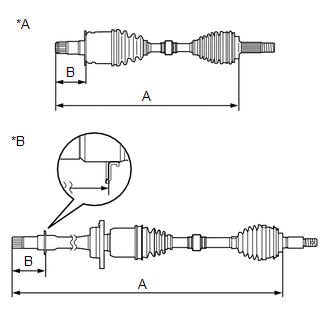
| (e) Check whether the drive shaft dimension (A) and (B) are within specification. NOTICE: Keep the drive shaft assembly level during inspection. Dimension (A):
Dimension (B) (TMC Made):
Dimension (B) (TMMK Made):
|
|
READ NEXT:
 Installation
INSTALLATION CAUTION / NOTICE / HINT HINT:
Use the same procedure for the RH side and LH side.
The following procedure is for the LH side.
PROCEDURE 1. INSTALL FRONT DRIVE SHAFT HOLE SNAP RING
Reassembly
REASSEMBLY CAUTION / NOTICE / HINT HINT:
Use the same procedure for the RH side and LH side.
The following procedure is for the LH side.
PROCEDURE 1. INSTALL FRONT AXLE OUTBOARD JOINT BOOT (a)
Removal
REMOVAL CAUTION / NOTICE / HINT The necessary procedures (adjustment, calibration, initialization, or registration) that must be performed after parts are removed and installed, or replaced during fro
SEE MORE:
Motor Electronics Coolant Pump "A" No Signal (P314A31)
DESCRIPTION Refer to the description for DTC P0C7396. Click here The inverter water pump assembly sends the inverter water pump speed (measured value) signal to the hybrid vehicle control ECU. DTC No. Detection Item DTC Detection Condition Trouble Area MIL Warning Indicate P314A31
Diagnostic Trouble Code Chart
DIAGNOSTIC TROUBLE CODE CHART Lane Control System DTC No. Detection Item Link C1A7496 Steering Vibrator Component Internal Failure U012587 Lost Communication with Multi-axis Acceleration Sensor Module Missing Message U012687 Lost Communication with Steering Angle S
