Lexus ES: Installation
INSTALLATION
CAUTION / NOTICE / HINT
HINT:
- Use the same procedure for the RH side and LH side.
- The following procedure is for the LH side.
PROCEDURE
1. INSTALL FRONT DRIVE SHAFT HOLE SNAP RING
(a) Install a new front drive shaft hole snap ring.
NOTICE:
Face the end gap of the front drive shaft hole snap ring downward.
2. INSTALL FRONT DRIVE SHAFT ASSEMBLY LH
(a) Coat the snap ring of the front drive inboard joint assembly with MP grease.
(b) Coat the splines of the front drive inboard joint assembly with Toyota genuine ATF WS.
(c) Coat the lip of the front drive shaft oil seal LH with MP grease and Toyota genuine oil seal side lip grease as shown in the illustration.
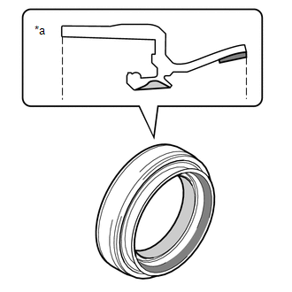
| *a | Cross Section of Front Drive Shaft Oil Seal LH |
 | MP Grease |
 | Toyota Genuine Oil Seal Side Lip Grease |
HINT:
Apply a light coat of MP grease and Toyota genuine oil seal side lip grease to the entire circumference of the front drive shaft oil seal LH.
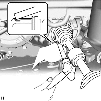
| (d) Align the inboard joint splines, and using a brass bar and a hammer, install the front drive shaft assembly LH. NOTICE:
HINT: Confirm whether the drive shaft is securely driven in by checking the reaction force and sound. |
|
(e) Apply 0.1 to 0.3 g (0.00353 to 0.0105 oz) of Toyota Body Grease W to each of the 4 areas shown in the illustration.
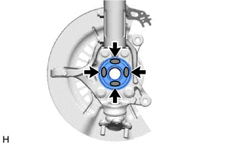
.png) | Toyota Body Grease W |
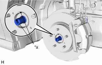
| (f) Align the matchmarks and install the front drive shaft assembly LH to the front axle assembly. NOTICE:
|
|
3. INSTALL FRONT DRIVE SHAFT ASSEMBLY RH
(a) Coat the splines of the front drive inboard joint assembly with Toyota genuine ATF WS.
(b) Coat the lip of the front drive shaft oil seal RH with MP grease and Toyota genuine oil seal side lip grease as shown in the illustration.
HINT:
Apply a light coat of Toyota genuine oil seal side lip grease to the entire circumference of the front drive shaft oil seal RH.

| *a | Cross Section of Front Drive Shaft Oil Seal RH |
| | MP Grease |
| | Toyota Genuine Oil Seal Side Lip Grease |
(c) Align the inboard joint splines, and securely insert the front drive shaft assembly RH.
NOTICE:
- Do not damage the front drive shaft oil seal RH.
- Do not damage the front axle inboard joint boot.
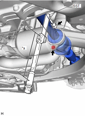
| (d) Install the front drive shaft assembly RH with the 2 bolts. SST: 09961-00950 Torque: Specified tightening torque : 50.5 N·m {515 kgf·cm, 37 ft·lbf} HINT:
|
|
(e) Apply 0.1 to 0.3 g (0.00353 to 0.0105 oz) of Toyota Body Grease W to each of the 4 areas shown in the illustration.
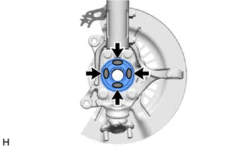
| | Toyota Body Grease W |
| (f) Align the matchmarks and install the front drive shaft assembly RH to the front axle assembly. NOTICE:
|
|
4. CONNECT FRONT LOWER NO. 1 SUSPENSION ARM SUB-ASSEMBLY
Click here .gif)
5. INSTALL FRONT STABILIZER LINK ASSEMBLY
Click here
6. CONNECT TIE ROD ASSEMBLY
Click here
7. INSTALL FRONT SPEED SENSOR (w/o AVS)
Click here
8. INSTALL FRONT SPEED SENSOR (w/ AVS)
Click here
9. INSTALL FRONT AXLE SHAFT NUT
(a) Clean the threaded parts on the front drive shaft assembly and a new front axle shaft nut using non-residue solvent.
NOTICE:
- Make sure to perform this work even when using a new front drive shaft assembly.
- Keep the threaded parts free of oil and foreign matter.
| (b) Using a 30 mm deep socket wrench, install the front axle shaft nut. Torque: 294 N·m {2998 kgf·cm, 217 ft·lbf} HINT: Depress the brake pedal to prevent the drive shaft from rotating. |
|
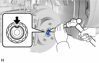
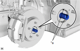
(c) Using a chisel and hammer, stake the front axle shaft nut.
10. ADD AUTOMATIC TRANSAXLE FLUID
Click here
11. INSTALL FRONT WHEELS
Click here
12. INSPECT AND ADJUST FRONT WHEEL ALIGNMENT
Click here
13. INSTALL FRONT FENDER APRON SEAL LH
Click here
14. INSTALL FRONT FENDER APRON SEAL RH
Click here
15. INSTALL NO. 2 ENGINE UNDER COVER
Click here
16. INSTALL NO. 3 ENGINE UNDER COVER
Click here
17. INSTALL NO. 1 ENGINE UNDER COVER
Click here
18. INSTALL FRONT WHEEL OPENING EXTENSION PAD LH
Click here
19. INSTALL FRONT WHEEL OPENING EXTENSION PAD RH
Click here
20. CHECK FOR SPEED SENSOR SIGNAL
Click here
READ NEXT:
 Reassembly
REASSEMBLY CAUTION / NOTICE / HINT HINT:
Use the same procedure for the RH side and LH side.
The following procedure is for the LH side.
PROCEDURE 1. INSTALL FRONT AXLE OUTBOARD JOINT BOOT (a)
Removal
REMOVAL CAUTION / NOTICE / HINT The necessary procedures (adjustment, calibration, initialization, or registration) that must be performed after parts are removed and installed, or replaced during fro
SEE MORE:
Removal
REMOVAL CAUTION / NOTICE / HINT The necessary procedures (adjustment, calibration, initialization or registration) that must be performed after parts are removed and installed, or replaced during inverter with converter assembly removal/installation are shown below. Necessary Procedures After Parts
Data List / Active Test
DATA LIST / ACTIVE TEST DATA LIST NOTICE:
Some Data List values may vary significantly if there are slight differences in the environment in which the vehicle is operating when measurements are obtained. Variations may also occur due to aging of the vehicle. Due to these considerations, it is not
