Lexus ES: Lost Communication with Haptic Device (B1323-B1326)
DESCRIPTION
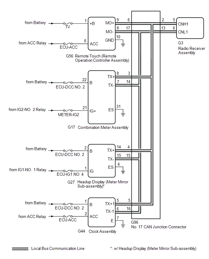
These DTCs are stored when communication between the radio receiver assembly and remote touch (remote operation controller assembly), combination meter assembly, headup display (meter mirror sub-assembly)* or clock assembly is not possible.
- *: w/ Headup Display System
| DTC No. | Detection Item | DTC Detection Condition | Trouble Area |
|---|---|---|---|
| B1323 | Lost Communication with Haptic Device | CAN reception error |
|
| B1324 | Lost Communication with Meter | CAN reception error |
|
| B1325 | Lost Communication with HUD | CAN reception error |
|
| B1326 | Lost Communication with Clock Device (Local-CAN) | CAN reception error |
|
HINT:
The radio receiver assembly is the master unit.
WIRING DIAGRAM
CAUTION / NOTICE / HINT
NOTICE:
-
Depending on the parts that are replaced during vehicle inspection or maintenance, performing initialization, registration or calibration may be needed. Refer to Precaution for Navigation System.
Click here
.gif)
-
When replacing the radio receiver assembly, always replace it with a new one. If a radio receiver assembly which was installed to another vehicle is used, the following may occur:
- A communication malfunction DTC may be stored.
- The radio receiver assembly may not operate normally.
- Inspect the fuses for circuits related to this system before performing the following procedure.
PROCEDURE
| 1. | CHECK DTC |
(a) Check for DTCs.
Body Electrical > Navigation System > Trouble Codes| Result | Proceed to |
|---|---|
| DTC B1323, B1324, B1325* and B1326 are not output | A |
| DTC B1323, B1324, B1325* and B1326 are output | B |
| DTC B1323 is output | C |
| DTC B1324 is output | D |
| DTC B1325 is output | E |
| DTC B1326 is output | F |
| A |  | USE SIMULATION METHOD TO CHECK |
| C | | GO TO STEP 17 |
| D | | GO TO STEP 19 |
| E | | GO TO STEP 21 |
| F | | GO TO STEP 23 |
|

| 2. | CHECK LOCAL BUS |
(a) Disconnect the cable from the negative (-) battery terminal.
(b) Measure the resistance according to the value(s) in the table below.
Standard Resistance:
| Tester Connection | Condition | Specified Condition |
|---|---|---|
| G96-2 - G96-13 | Cable disconnected from negative (-) battery terminal | 54 to 69 Ω |
| Result | Proceed to |
|---|---|
| OK | A |
| NG (Below 54 Ω) | B |
| NG (70 Ω or higher) | C |
| A | | USE SIMULATION METHOD TO CHECK |
| C | | GO TO STEP 13 |
|
| 3. | CHECK HARNESS AND CONNECTOR (NO. 17 CAN JUNCTION CONNECTOR - RADIO RECEIVER ASSEMBLY) |
(a) Disconnect the cable from the negative (-) battery terminal.
(b) Disconnect the G96 No. 17 CAN junction connector.
(c) Connect the G3 radio receiver assembly connector.
(d) Measure the resistance according to the value(s) in the table below.
Standard Resistance:
| Tester Connection | Condition | Specified Condition |
|---|---|---|
| G96-2 - G96-13 | Cable disconnected from negative (-) battery terminal | 108 to 132 Ω |
| NG | | GO TO STEP 12 |
|
| 4. | CHECK HARNESS AND CONNECTOR (NO. 17 CAN JUNCTION CONNECTOR - REMOTE TOUCH (REMOTE OPERATION CONTROLLER ASSEMBLY)) |
(a) Disconnect the cable from the negative (-) battery terminal.
(b) Disconnect the G96 No. 17 CAN junction connector.
(c) Connect the G56 remote touch (remote operation controller assembly) connector.
(d) Measure the resistance according to the value(s) in the table below.
Standard Resistance:
| Tester Connection | Condition | Specified Condition |
|---|---|---|
| G96-6 - G96-17 | Cable disconnected from negative (-) battery terminal | 108 to 132 Ω |
| NG | | GO TO STEP 11 |
|
| 5. | CHECK HARNESS AND CONNECTOR (NO. 17 CAN JUNCTION CONNECTOR - COMBINATION METER ASSEMBLY) |
(a) Disconnect the cable from the negative (-) battery terminal.
(b) Disconnect the G96 No. 17 CAN junction connector.
(c) Connect the G17 combination meter assembly connector.
(d) Measure the resistance according to the value(s) in the table below.
Standard Resistance:
| Tester Connection | Condition | Specified Condition |
|---|---|---|
| G96-3 - G96-14 | Cable disconnected from negative (-) battery terminal | 200 Ω or higher |
| NG | | GO TO STEP 10 |
|
| 6. | CHECK HARNESS AND CONNECTOR (NO. 17 CAN JUNCTION CONNECTOR - CLOCK ASSEMBLY) |
(a) Disconnect the cable from the negative (-) battery terminal.
(b) Disconnect the G96 No. 17 CAN junction connector.
(c) Connect the G44 clock assembly connector.
(d) Measure the resistance according to the value(s) in the table below.
Standard Resistance:
| Tester Connection | Condition | Specified Condition |
|---|---|---|
| G96-5 - G96-16 | Cable disconnected from negative (-) battery terminal | 200 Ω or higher |
| Result | Proceed to |
|---|---|
| OK (w/o Headup Display System) | A |
| OK (w/ Headup Display System) | B |
| NG | C |
| A | | REPLACE NO. 17 CAN JUNCTION CONNECTOR |
| C | | GO TO STEP 9 |
|
| 7. | CHECK HARNESS AND CONNECTOR (NO. 17 CAN JUNCTION CONNECTOR - HEADUP DISPLAY (METER MIRROR SUB-ASSEMBLY)) |
(a) Disconnect the cable from the negative (-) battery terminal.
(b) Disconnect the G96 No. 17 CAN junction connector.
(c) Connect the G27 headup display (meter mirror sub-assembly) connector.
(d) Measure the resistance according to the value(s) in the table below.
Standard Resistance:
| Tester Connection | Condition | Specified Condition |
|---|---|---|
| G96-4 - G96-15 | Cable disconnected from negative (-) battery terminal | 200 Ω or higher |
| OK | | REPLACE NO. 17 CAN JUNCTION CONNECTOR |
|
| 8. | CHECK HARNESS AND CONNECTOR (HEADUP DISPLAY (METER MIRROR SUB-ASSEMBLY) - NO. 17 CAN JUNCTION CONNECTOR) |
(a) Disconnect the cable from the negative (-) battery terminal.
(b) Disconnect the G27 headup display (meter mirror sub-assembly) connector.
(c) Connect the G96 No. 17 CAN junction connector.
(d) Measure the resistance according to the value(s) in the table below.
Standard Resistance:
| Tester Connection | Condition | Specified Condition |
|---|---|---|
| G27-14 (TX+) - G27-15 (TX-) | Cable disconnected from negative (-) battery terminal | 54 to 69 Ω |
| OK | | REPLACE HEADUP DISPLAY (METER MIRROR SUB-ASSEMBLY) |
| NG | | REPAIR OR REPLACE HARNESS OR CONNECTOR |
| 9. | CHECK HARNESS AND CONNECTOR (CLOCK ASSEMBLY - NO. 17 CAN JUNCTION CONNECTOR) |
(a) Disconnect the cable from the negative (-) battery terminal.
(b) Disconnect the G44 clock assembly connector.
(c) Connect the G96 No. 17 CAN junction connector.
(d) Measure the resistance according to the value(s) in the table below.
Standard Resistance:
| Tester Connection | Condition | Specified Condition |
|---|---|---|
| G44-5 (TX+1) - G44-6 (TX-1) | Cable disconnected from negative (-) battery terminal | 54 to 69 Ω |
| OK | | REPLACE CLOCK ASSEMBLY |
| NG | | REPAIR OR REPLACE HARNESS OR CONNECTOR |
| 10. | CHECK HARNESS AND CONNECTOR (COMBINATION METER ASSEMBLY - NO. 17 CAN JUNCTION CONNECTOR) |
(a) Disconnect the cable from the negative (-) battery terminal.
(b) Disconnect the G17 combination meter assembly connector.
(c) Connect the G96 No. 17 CAN junction connector.
(d) Measure the resistance according to the value(s) in the table below.
Standard Resistance:
| Tester Connection | Condition | Specified Condition |
|---|---|---|
| G17-8 (TX+) - G17-7 (TX-) | Cable disconnected from negative (-) battery terminal | 54 to 69 Ω |
| OK | | REPLACE COMBINATION METER ASSEMBLY |
| NG | | REPAIR OR REPLACE HARNESS OR CONNECTOR |
| 11. | CHECK HARNESS AND CONNECTOR (REMOTE TOUCH (REMOTE OPERATION CONTROLLER ASSEMBLY) - NO. 17 CAN JUNCTION CONNECTOR) |
(a) Disconnect the cable from the negative (-) battery terminal.
(b) Disconnect the G56 remote touch (remote operation controller assembly) connector.
(c) Connect the G96 No. 17 CAN junction connector.
(d) Measure the resistance according to the value(s) in the table below.
Standard Resistance:
| Tester Connection | Condition | Specified Condition |
|---|---|---|
| G56-9 (MO+) - G56-8 (MO-) | Cable disconnected from negative (-) battery terminal | 108 to 132 Ω |
| OK | | REPLACE REMOTE TOUCH (REMOTE OPERATION CONTROLLER ASSEMBLY) |
| NG | | REPAIR OR REPLACE HARNESS OR CONNECTOR |
| 12. | CHECK HARNESS AND CONNECTOR (RADIO RECEIVER ASSEMBLY - NO. 17 CAN JUNCTION CONNECTOR) |
(a) Disconnect the cable from the negative (-) battery terminal.
(b) Disconnect the G3 radio receiver assembly connector.
(c) Connect the G96 No. 17 CAN junction connector.
(d) Measure the resistance according to the value(s) in the table below.
Standard Resistance:
| Tester Connection | Condition | Specified Condition |
|---|---|---|
| G3-5 (CNH1) - G3-6 (CNL1) | Cable disconnected from negative (-) battery terminal | 108 to 132 Ω |
| OK | | REPLACE RADIO RECEIVER ASSEMBLY |
| NG | | REPAIR OR REPLACE HARNESS OR CONNECTOR |
| 13. | CHECK HARNESS AND CONNECTOR (NO. 17 CAN JUNCTION CONNECTOR - RADIO RECEIVER ASSEMBLY) |
(a) Disconnect the cable from the negative (-) battery terminal.
(b) Disconnect the G96 No. 17 CAN junction connector.
(c) Connect the G3 radio receiver assembly connector.
(d) Measure the resistance according to the value(s) in the table below.
Standard Resistance:
| Tester Connection | Condition | Specified Condition |
|---|---|---|
| G96-2 - G96-13 | Cable disconnected from negative (-) battery terminal | 108 to 132 Ω |
| NG | | GO TO STEP 16 |
|
| 14. | CHECK HARNESS AND CONNECTOR (NO. 17 CAN JUNCTION CONNECTOR - REMOTE TOUCH (REMOTE OPERATION CONTROLLER ASSEMBLY)) |
(a) Disconnect the cable from the negative (-) battery terminal.
(b) Disconnect the G96 No. 17 CAN junction connector.
(c) Connect the G56 remote touch (remote operation controller assembly) connector.
(d) Measure the resistance according to the value(s) in the table below.
Standard Resistance:
| Tester Connection | Condition | Specified Condition |
|---|---|---|
| G96-6 - G96-17 | Cable disconnected from negative (-) battery terminal | 108 to 132 Ω |
| OK | | REPLACE NO. 17 CAN JUNCTION CONNECTOR |
|
| 15. | CHECK HARNESS AND CONNECTOR (REMOTE TOUCH (REMOTE OPERATION CONTROLLER ASSEMBLY) - NO. 17 CAN JUNCTION CONNECTOR) |
(a) Disconnect the cable from the negative (-) battery terminal.
(b) Disconnect the G56 remote touch (remote operation controller assembly) connector.
(c) Connect the G96 No. 17 CAN junction connector.
(d) Measure the resistance according to the value(s) in the table below.
Standard Resistance:
| Tester Connection | Condition | Specified Condition |
|---|---|---|
| G56-9 (MO+) - G56-8 (MO-) | Cable disconnected from negative (-) battery terminal | 108 to 132 Ω |
| OK | | REPLACE REMOTE TOUCH (REMOTE OPERATION CONTROLLER ASSEMBLY) |
| NG | | REPAIR OR REPLACE HARNESS OR CONNECTOR |
| 16. | CHECK HARNESS AND CONNECTOR (RADIO RECEIVER ASSEMBLY - NO. 17 CAN JUNCTION CONNECTOR) |
(a) Disconnect the cable from the negative (-) battery terminal.
(b) Disconnect the G3 radio receiver assembly connector.
(c) Connect the G96 No. 17 CAN junction connector.
(d) Measure the resistance according to the value(s) in the table below.
Standard Resistance:
| Tester Connection | Condition | Specified Condition |
|---|---|---|
| G3-5 (CNH1) - G3-6 (CNL1) | Cable disconnected from negative (-) battery terminal | 108 to 132 Ω |
| OK | | REPLACE RADIO RECEIVER ASSEMBLY |
| NG | | REPAIR OR REPLACE HARNESS OR CONNECTOR |
| 17. | CHECK HARNESS AND CONNECTOR (REMOTE TOUCH (REMOTE OPERATION CONTROLLER ASSEMBLY) POWER SOURCE) |
(a) Disconnect the G56 remote touch (remote operation controller assembly) connector.
(b) Measure the resistance according to the value(s) in the table below.
Standard Resistance:
| Tester Connection | Condition | Specified Condition |
|---|---|---|
| G56-10 (GND) - Body ground | Always | Below 1 Ω |
(c) Measure the voltage according to the value(s) in the table below.
Standard Voltage:
| Tester Connection | Condition | Specified Condition |
|---|---|---|
| G56-1 (+B) - Body ground | Always | 11 to 14 V |
| G56-6 (ACC) - Body ground | Engine switch on (ACC) | 11 to 14 V |
| NG | | REPAIR OR REPLACE HARNESS OR CONNECTOR |
|
| 18. | CHECK HARNESS AND CONNECTOR (REMOTE TOUCH (REMOTE OPERATION CONTROLLER ASSEMBLY) - NO. 17 CAN JUNCTION CONNECTOR) |
(a) Disconnect the cable from the negative (-) battery terminal.
(b) Disconnect the G56 remote touch (remote operation controller assembly) connector.
(c) Connect the G96 No. 17 CAN junction connector.
(d) Measure the resistance according to the value(s) in the table below.
Standard Resistance:
| Tester Connection | Condition | Specified Condition |
|---|---|---|
| G56-9 (MO+) - G56-8 (MO-) | Cable disconnected from negative (-) battery terminal | 108 to 132 Ω |
| OK | | REPLACE REMOTE TOUCH (REMOTE OPERATION CONTROLLER ASSEMBLY) |
| NG | | REPAIR OR REPLACE HARNESS OR CONNECTOR |
| 19. | CHECK HARNESS AND CONNECTOR (COMBINATION METER ASSEMBLY POWER SOURCE) |
(a) Disconnect the G17 combination meter assembly connector.
(b) Measure the resistance according to the value(s) in the table below.
Standard Resistance:
| Tester Connection | Condition | Specified Condition |
|---|---|---|
| G17-31 (ES) - Body ground | Always | Below 1 Ω |
(c) Measure the voltage according to the value(s) in the table below.
Standard Voltage:
| Tester Connection | Condition | Specified Condition |
|---|---|---|
| G17-22 (B) - Body ground | Always | 11 to 14 V |
| G17-21 (IG+) - Body ground | Engine switch on (IG) | 11 to 14 V |
| NG | | REPAIR OR REPLACE HARNESS OR CONNECTOR |
|
| 20. | CHECK HARNESS AND CONNECTOR (COMBINATION METER ASSEMBLY - NO. 17 CAN JUNCTION CONNECTOR) |
(a) Disconnect the cable from the negative (-) battery terminal.
(b) Disconnect the G17 combination meter assembly connector.
(c) Connect the G96 No. 17 CAN junction connector.
(d) Measure the resistance according to the value(s) in the table below.
Standard Resistance:
| Tester Connection | Condition | Specified Condition |
|---|---|---|
| G17-8 (TX+) - G17-7 (TX-) | Cable disconnected from negative (-) battery terminal | 54 to 69 Ω |
| OK | | REPLACE COMBINATION METER ASSEMBLY |
| NG | | REPAIR OR REPLACE HARNESS OR CONNECTOR |
| 21. | CHECK HARNESS AND CONNECTOR (HEADUP DISPLAY (METER MIRROR SUB-ASSEMBLY) POWER SOURCE) |
(a) Disconnect the G27 headup display (meter mirror sub-assembly) connector.
(b) Measure the resistance according to the value(s) in the table below.
Standard Resistance:
| Tester Connection | Condition | Specified Condition |
|---|---|---|
| G27-4 (ES) - Body ground | Always | Below 1 Ω |
(c) Measure the voltage according to the value(s) in the table below.
Standard Voltage:
| Tester Connection | Condition | Specified Condition |
|---|---|---|
| G27-2 (B) - Body ground | Always | 11 to 14 V |
| G27-1 (IG) - Body ground | Engine switch on (IG) | 11 to 14 V |
| NG | | REPAIR OR REPLACE HARNESS OR CONNECTOR |
|
| 22. | CHECK HARNESS AND CONNECTOR (HEADUP DISPLAY (METER MIRROR SUB-ASSEMBLY) - NO. 17 CAN JUNCTION CONNECTOR) |
(a) Disconnect the cable from the negative (-) battery terminal.
(b) Disconnect the G27 headup display (meter mirror sub-assembly) connector.
(c) Connect the G96 No. 17 CAN junction connector.
(d) Measure the resistance according to the value(s) in the table below.
Standard Resistance:
| Tester Connection | Condition | Specified Condition |
|---|---|---|
| G27-14 (TX+) - G27-15 (TX-) | Cable disconnected from negative (-) battery terminal | 54 to 69 Ω |
| OK | | REPLACE HEADUP DISPLAY (METER MIRROR SUB-ASSEMBLY) |
| NG | | REPAIR OR REPLACE HARNESS OR CONNECTOR |
| 23. | CHECK HARNESS AND CONNECTOR (CLOCK ASSEMBLY POWER SOURCE) |
(a) Disconnect the G44 clock assembly connector.
(b) Measure the resistance according to the value(s) in the table below.
Standard Resistance:
| Tester Connection | Condition | Specified Condition |
|---|---|---|
| G44-7 (E) - Body ground | Always | Below 1 Ω |
(c) Measure the voltage according to the value(s) in the table below.
Standard Voltage:
| Tester Connection | Condition | Specified Condition |
|---|---|---|
| G44-1 (B) - Body ground | Always | 11 to 14 V |
| G44-2 (ACC) - Body ground | Engine switch on (ACC) | 11 to 14 V |
| NG | | REPAIR OR REPLACE HARNESS OR CONNECTOR |
|
| 24. | CHECK HARNESS AND CONNECTOR (CLOCK ASSEMBLY - NO. 17 CAN JUNCTION CONNECTOR) |
(a) Disconnect the cable from the negative (-) battery terminal.
(b) Disconnect the G44 clock assembly connector.
(c) Connect the G96 No. 17 CAN junction connector.
(d) Measure the resistance according to the value(s) in the table below.
Standard Resistance:
| Tester Connection | Condition | Specified Condition |
|---|---|---|
| G44-5 (TX+1) - G44-6 (TX-1) | Cable disconnected from negative (-) battery terminal | 54 to 69 Ω |
| OK | | REPLACE CLOCK ASSEMBLY |
| NG | | REPAIR OR REPLACE HARNESS OR CONNECTOR |
READ NEXT:
 NTSC Disconnected (from Park Assist/Monitoring ECU) (B1535,C1622)
DESCRIPTION These DTCs are stored if the radio receiver assembly judges that the signals or signal lines between the rear television camera assembly and the multi-display assembly are not normal as a
Extension Module Disconnected 2 (B1543)
DESCRIPTION If the radio receiver assembly cannot detect the navigation ECU for a certain period of time (90 seconds) after the engine switch is turned on (ACC) and the radio receiver assembly confirm
HD Radio Tuner Malfunction (B1551,B15A0,B15B3-B15B5,B15B7,B15BA,B15F9)
DESCRIPTION These DTCs are stored when a malfunction occurs in the radio receiver assembly DTC No. Detection Item DTC Detection Condition Trouble Area B1551 HD Radio Tuner Malfunction
SEE MORE:
Precaution
PRECAUTION PRECAUTION FOR DISCONNECTING CABLE FROM NEGATIVE AUXILIARY BATTERY TERMINAL NOTICE: When disconnecting the cable from the negative (-) auxiliary battery terminal, initialize the following systems after the cable is reconnected. System Name See Procedure Lane Control System (for G
Definition Of Terms
DEFINITION OF TERMS Term Definition Monitor description Description of what the ECM monitors and how it detects malfunctions (monitoring purpose and details). Related DTCs Group of diagnostic trouble codes that are output by the ECM based on the same malfunction detection logic.
