Lexus ES: Reassembly
REASSEMBLY
CAUTION / NOTICE / HINT
HINT:
- Use the same procedure for the RH side and LH side.
- The following procedure is for the LH side.
PROCEDURE
1. INSTALL FRONT AXLE OUTBOARD JOINT BOOT
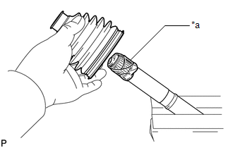
(a) Secure the drive shaft in a vise between aluminum plates.
NOTICE:
Do not overtighten the vise.
| (b) Wrap the splines of the front drive outboard joint shaft assembly with protective tape to prevent the boot from being damaged. |
|
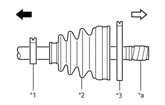
(c) Install new parts to the front drive outboard joint shaft assembly in the following order:
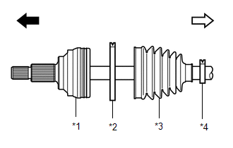
| *1 | Front Drive Outboard Joint Shaft Assembly |
| *2 | Front No. 2 Axle Outboard Joint Boot Clamp |
| *3 | Front Axle Outboard Joint Boot |
| *4 | Front Axle Outboard Joint Boot Clamp |
.png) | Outboard Joint Side |
.png) | Inboard Joint Side |
(1) Front No. 2 axle outboard joint boot clamp
(2) Front axle outboard joint boot
(3) Front axle outboard joint boot clamp
(d) Pack the joint portion of the front drive outboard joint shaft assembly and front axle outboard joint boot with grease.
Standard Grease Capacity:
81 to 91 g (2.86 to 3.20 oz)
(e) Install the front axle outboard joint boot to the front drive outboard joint shaft assembly groove.
NOTICE:
- Do not allow grease to adhere to the boot clamp track of the outboard joint boot.
- Keep the inside of the outboard joint boot free of foreign matter.
2. INSTALL FRONT AXLE OUTBOARD JOINT BOOT CLAMP
(a) Secure the drive shaft in a vise between aluminum plates.
NOTICE:
Do not overtighten the vise.
(b) Install the front axle outboard joint boot clamp to the front axle outboard joint boot.
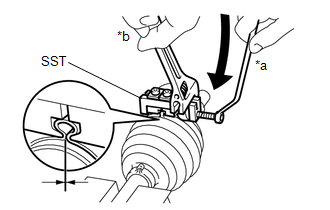
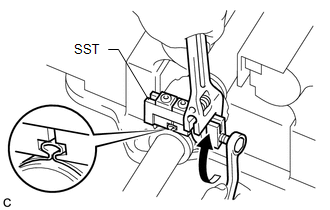
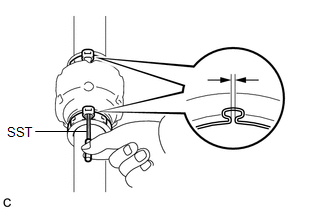
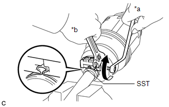
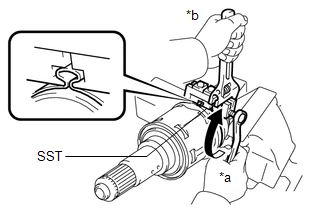
| (c) Place SST to the front axle outboard joint boot clamp, press it against the boot and slightly tighten SST. SST: 09521-24010 |
|
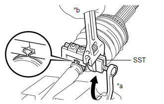
(d) Tighten SST so that the front axle outboard joint boot clamp is pinched.
NOTICE:
Do not overtighten SST.
(e) Remove SST.
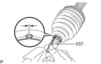
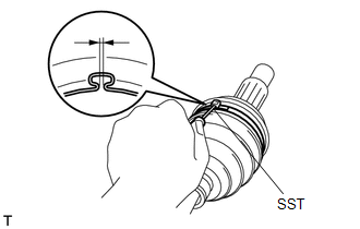
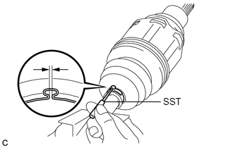
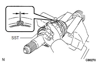
| (f) Using SST, measure the clearance of the front axle outboard joint boot clamp. SST: 09240-00021 Clearance: 0.5 to 1.5 mm (0.0197 to 0.0590 in.) If the clearance is not as specified, retighten SST. |
|
3. INSTALL FRONT NO. 2 AXLE OUTBOARD JOINT BOOT CLAMP
(a) Secure the drive shaft in a vise between aluminum plates.
NOTICE:
Do not overtighten the vise.
(b) Install the front No. 2 axle outboard joint boot clamp to the front axle outboard joint boot.
| (c) Place SST onto the front No. 2 axle outboard joint boot clamp, press it against the boot and slightly tighten SST. SST: 09521-24010 |
|
(d) Tighten SST so that the front No. 2 axle outboard joint boot clamp is pinched.
NOTICE:
Do not overtighten SST.
(e) Remove SST.
| (f) Using SST, measure the clearance of the front No. 2 axle outboard joint boot clamp. SST: 09240-00021 Clearance: 0.5 to 1.5 mm (0.0197 to 0.0590 in.) If the clearance is not as specified, retighten SST. |
|
4. INSTALL FRONT DRIVE SHAFT DAMPER
| (a) Temporarily install the front drive shaft damper and 2 new front drive shaft damper clamps to the front drive outboard joint shaft assembly as shown in the illustration. |
|
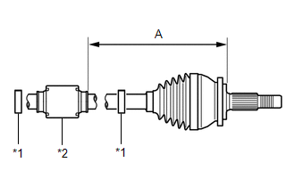
(b) Set the dimension (A) as specified below.
Dimension (A):
226.9 to 230.9 mm (8.94 to 9.09 in.)
5. INSTALL FRONT DRIVE SHAFT DAMPER CLAMP (for LH Side)
(a) Secure the drive shaft in a vise between aluminum plates.
NOTICE:
Do not overtighten the vise.
(b) Install the 2 front drive shaft damper clamps to the front drive shaft damper.
NOTICE:
Make sure to install the clamps in the correct position.
| (c) Place SST onto the front drive shaft damper clamp, press it against the damper and slightly tighten SST. SST: 09521-24010 |
|
(d) Tighten SST so that the front drive shaft damper clamp is pinched.
NOTICE:
Do not overtighten SST.
(e) Remove SST.
| (f) Using SST, measure the clearance of the front drive shaft damper clamp. SST: 09240-00021 Clearance: 0.5 to 1.5 mm (0.0197 to 0.0590 in.) If the clearance is not as specified, retighten SST. |
|
6. INSTALL FRONT DRIVE SHAFT DAMPER CLAMP (for RH Side)
(a) Secure the drive shaft in a vise between aluminum plates.
NOTICE:
Do not overtighten the vise.
| (b) Using needle-nose pliers, install the 2 front drive shaft damper clamps as shown in the illustration. NOTICE:
|
|
.png)
7. INSTALL FRONT DRIVE INBOARD JOINT ASSEMBLY
(a) Install new parts to the front drive outboard joint shaft assembly in the following order:
| *1 | Front Axle Inboard Joint Boot Clamp |
| *2 | Front Axle Inboard Joint Boot |
| *3 | Front No. 2 Axle Inboard Joint Boot Clamp |
| *a | Protective Tape |
| | Outboard Joint Side |
| | Inboard Joint Side |
(1) Front axle inboard joint boot clamp
(2) Front axle inboard joint boot
(3) Front No. 2 axle inboard joint boot clamp
(b) Secure the drive shaft in a vise between aluminum plates.
NOTICE:
Do not overtighten the vise.
(c) Remove the protective tape.
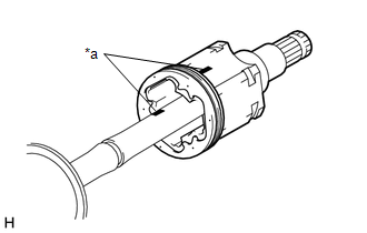
| (d) Align the matchmarks and install the tripod joint to the front drive outboard joint shaft assembly. NOTICE: Face the serrated side of the tripod joint outward and install it to the outboard joint end. |
|
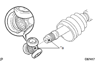
(e) Using a brass bar and a hammer, install the tripod joint to the front drive outboard joint shaft assembly.
NOTICE:
- Do not tap the rollers.
- Keep the tripod joint free of foreign matter.
- Be sure to install the tripod joint in the correct direction.
| (f) Using a snap ring expander, install a new shaft snap ring to the front drive outboard joint shaft assembly. |
|
.png)
(g) Pack the front drive inboard joint assembly and front axle inboard joint boot with grease.
Standard Grease Capacity:
190 to 200 g (6.71 to 7.05 oz)
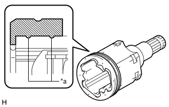
| (h) Install a new front axle inboard joint grommet to the front drive inboard joint assembly. NOTICE:
|
|
| (i) Align the matchmarks and install the front drive inboard joint assembly to the front drive outboard joint shaft assembly. |
|
8. INSTALL FRONT AXLE INBOARD JOINT BOOT
(a) Install the front axle inboard joint boot to the front drive inboard joint assembly.
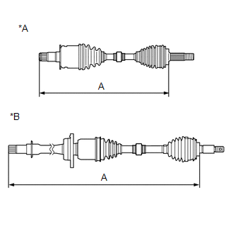
| (b) Check whether the dimension (A) of each drive shaft is within the specification. NOTICE: Keep the drive shaft assembly level during inspection. Dimension (A):
|
|
9. INSTALL FRONT AXLE INBOARD JOINT BOOT CLAMP
(a) Secure the drive shaft in a vise between aluminum plates.
NOTICE:
Do not overtighten the vise.
(b) Install the front axle inboard joint boot clamp to the front axle inboard joint boot.
| (c) Place SST onto the front axle inboard joint boot clamp, press it against the boot and slightly tighten SST. SST: 09521-24010 |
|
(d) Tighten SST so that the front axle inboard joint boot clamp is pinched.
NOTICE:
Do not overtighten SST.
(e) Remove SST.
| (f) Using SST, measure the clearance of the front axle inboard joint boot clamp. SST: 09240-00021 Clearance: 0.5 to 1.5 mm (0.0197 to 0.0590 in.) If the clearance is not as specified, retighten SST. |
|
10. INSTALL FRONT NO. 2 AXLE INBOARD JOINT BOOT CLAMP
(a) Secure the drive shaft in a vise between aluminum plates.
NOTICE:
Do not overtighten the vise.
(b) Install the front No. 2 axle inboard joint boot clamp to the front axle inboard joint boot.
| (c) Place SST onto the front No. 2 axle inboard joint boot clamp, press it against the boot and slightly tighten SST. SST: 09521-24010 |
|
(d) Tighten SST so that the front No. 2 axle inboard joint boot clamp is pinched.
NOTICE:
Do not overtighten SST.
(e) Remove SST.
| (f) Using SST, measure the clearance of the front No. 2 axle inboard joint boot clamp. SST: 09240-00021 Clearance: 0.5 to 1.5 mm (0.0197 to 0.0590 in.) If the clearance is not as specified, retighten SST. |
|
11. INSPECT FRONT DRIVE SHAFT ASSEMBLY
Click here .gif)
READ NEXT:
 Removal
REMOVAL CAUTION / NOTICE / HINT The necessary procedures (adjustment, calibration, initialization, or registration) that must be performed after parts are removed and installed, or replaced during fro
Components
COMPONENTS ILLUSTRATION *1 FRONT FENDER APRON SEAL LH *2 FRONT FENDER APRON SEAL RH *3 FRONT WHEEL OPENING EXTENSION PAD LH *4 FRONT WHEEL OPENING EXTENSION PAD RH *5 NO. 1 E
SEE MORE:
Removal
REMOVAL CAUTION / NOTICE / HINT The necessary procedures (adjustment, calibration, initialization or registration) that must be performed after parts are removed and installed, or replaced during air fuel ratio sensor removal/installation are shown below. Necessary Procedures After Parts Removed/Ins
Steering Angle Initialization Incomplete (C1694)
DESCRIPTION This DTC is stored when the rear television camera assembly judges that the maximum steering angle has not been memorized (steering angle setting is incomplete). DTC No. Detection Item DTC Detection Condition Trouble Area C1694 Steering Angle Initialization Incomplete Ma
