Lexus ES: Components
COMPONENTS
ILLUSTRATION
.png)
| *1 | BATTERY SERVICE HOLE COVER | *2 | SERVICE PLUG GRIP |
ILLUSTRATION
.png)
| *1 | CONNECTOR COVER ASSEMBLY | *2 | ENGINE ROOM MAIN WIRE |
.png) | Tightening torque for "Major areas involving basic vehicle performance such as moving/turning/stopping": N*m (kgf*cm, ft.*lbf) | .png) | N*m (kgf*cm, ft.*lbf): Specified torque |
ILLUSTRATION
.png)
| *1 | REAR UNDER COVER | *2 | REAR UNDER SIDE COVER LH |
| *3 | REAR UNDER SIDE COVER RH | *4 | REAR SEAT CUSHION LEG SUB-ASSEMBLY |
| *5 | REAR SEAT CUSHION ASSEMBLY | *6 | REAR DOOR SCUFF PLATE LH |
| *7 | REAR DOOR SCUFF PLATE RH | *8 | REAR SEAT CUSHION LOCK HOOK |
| *9 | REAR CENTER SEAT OUTER BELT ASSEMBLY | *10 | REAR SEAT INNER BELT ASSEMBLY RH |
| *11 | WASHER | - | - |
| | Tightening torque for "Major areas involving basic vehicle performance such as moving/turning/stopping": N*m (kgf*cm, ft.*lbf) | ● | Non-reusable part |
ILLUSTRATION
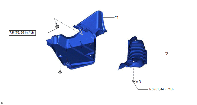
| *1 | NO. 1 FLOOR UNDER COVER | *2 | CENTER NO. 2 FLOOR HEAT INSULATOR |
| | N*m (kgf*cm, ft.*lbf): Specified torque | - | - |
ILLUSTRATION
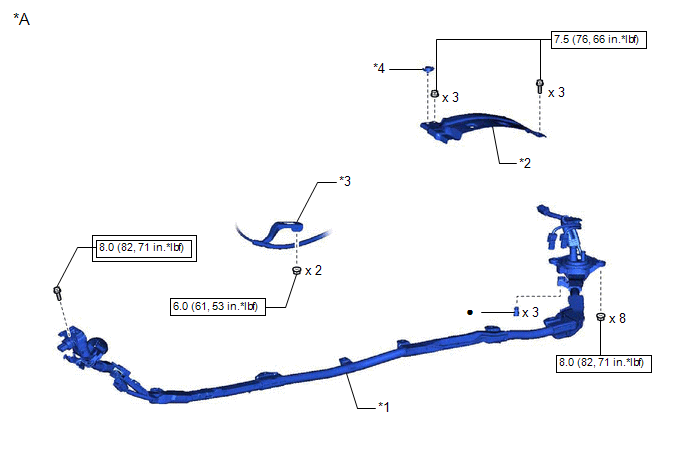
| *A | for NICKEL METAL HYDRIDE BATTERY | - | - |
| *1 | HV FLOOR UNDER WIRE | *2 | NO. 1 HV BATTERY COVER PANEL RH |
| *3 | TRANSMISSION CONTROL CABLE ASSEMBLY | *4 | BATTERY COVER LOCK STRIKER |
| | Tightening torque for "Major areas involving basic vehicle performance such as moving/turning/stopping": N*m (kgf*cm, ft.*lbf) | | N*m (kgf*cm, ft.*lbf): Specified torque |
| ● | Non-reusable part | - | - |
ILLUSTRATION
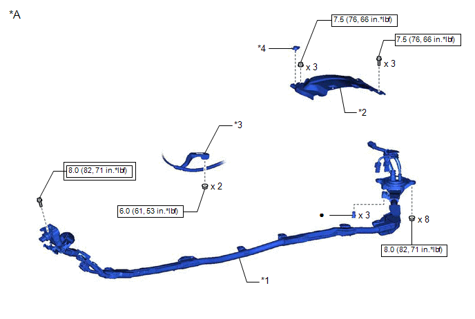
| *A | for LITHIUM-ION BATTERY | - | - |
| *1 | HV FLOOR UNDER WIRE | *2 | NO. 1 HV BATTERY COVER PANEL RH |
| *3 | TRANSMISSION CONTROL CABLE ASSEMBLY | *4 | BATTERY COVER LOCK STRIKER |
| | Tightening torque for "Major areas involving basic vehicle performance such as moving/turning/stopping": N*m (kgf*cm, ft.*lbf) | | N*m (kgf*cm, ft.*lbf): Specified torque |
| ● | Non-reusable part | - | - |
READ NEXT:
 Removal
REMOVAL CAUTION / NOTICE / HINT The necessary procedures (adjustment, calibration, initialization or registration) that must be performed after parts are removed and installed, or replaced during HV f
Installation
INSTALLATION PROCEDURE 1. INSTALL HV FLOOR UNDER WIRE CAUTION: Be sure to wear insulated gloves. (a) Insert the HV floor under wire into the floor panel hole and engage the grommet.
Installation
INSTALLATION PROCEDURE 1. INSTALL FLOOR UNDER WIRE CAUTION: Be sure to wear insulated gloves. (a) Insert the HV floor under wire into the floor panel hole and engage the grommet. (b)
SEE MORE:
Customize Parameters
CUSTOMIZE PARAMETERS CUSTOMIZE SLIDING ROOF SYSTEM HINT: The following items can be customized. NOTICE:
When the customer requests a change in a function, first make sure that the function can be customized.
Be sure to make a note of the current settings before customizing.
When troubleshooti
Steering Position Sensor (B2414)
DESCRIPTION The headlight ECU sub-assembly LH receives steering angle signals from the steering sensor via CAN communication and performs light control. for LED Type Turn Signal Light DTC No. Detection Item DTC Detection Condition Trouble Area DTC Output from B2414 Steering Position
