Lexus ES: Inspection
INSPECTION
PROCEDURE
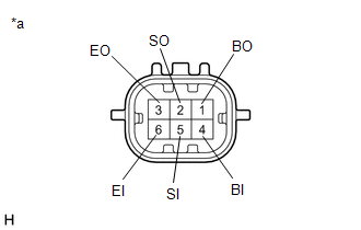
1. INSPECT FRONT CENTER ULTRASONIC SENSOR
| (a) Measure the resistance according to the value(s) in the table below. Standard Resistance:
If the result is not as specified, replace the front center ultrasonic sensor. |
|

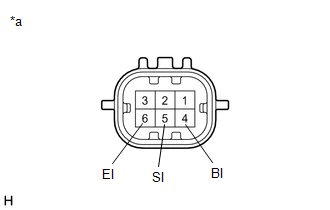
2. INSPECT FRONT CORNER ULTRASONIC SENSOR
(a) for RH Side:
| (1) Measure the resistance according to the value(s) in the table below. Standard Resistance:
If the result is not as specified, replace the front corner ultrasonic sensor RH. |
|
(b) for LH Side:
| (1) Measure the resistance according to the value(s) in the table below. Standard Resistance:
If the result is not as specified, replace the front corner ultrasonic sensor LH. |
|
READ NEXT:
 Installation
INSTALLATION PROCEDURE 1. INSTALL ULTRASONIC SENSOR CUSHION SET HINT: Only perform this procedure when removing and installing the ultrasonic sensor cushion set. (a) Install the ultrasonic sensor cush
Removal
REMOVAL CAUTION / NOTICE / HINT The necessary procedures (adjustment, calibration, initialization, or registration) that must be performed after parts are removed and installed, or replaced during ult
SEE MORE:
If a warning message is displayed
The multi-information display
shows warnings of system malfunctions,
incorrectly performed operations,
and messages that indicate a
need for maintenance. When a
message is shown, perform the correction
procedure appropriate to
the message.
Master warning light
The master warning lig
Disassembly
DISASSEMBLY PROCEDURE 1. REMOVE FRONT DRIVE SHAFT OIL SEAL RH (a) Hold the differential case assembly in a vise between aluminum plates. NOTICE: Do not overtighten the vise. (b) Using SST, remove the front drive shaft oil seal RH from the differential case assembly. SST: 09308-00010 N
