Lexus ES: Installation
INSTALLATION
PROCEDURE
1. INSTALL ULTRASONIC SENSOR CUSHION SET
HINT:
Only perform this procedure when removing and installing the ultrasonic sensor cushion set.
(a) Install the ultrasonic sensor cushion set as shown in the illustration.
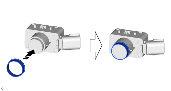
.png) | Install in this Direction | - | - |
2. INSTALL FRONT CORNER ULTRASONIC SENSOR RETAINER
HINT:
- Perform this procedure only when replacement of the front corner ultrasonic sensor retainer is necessary.
- If a front corner ultrasonic sensor retainer has been removed, replace it with a new one. Install the front corner ultrasonic sensor with a new front corner ultrasonic sensor retainer as a set to the front bumper assembly.
- The illustration is for the LH side. The orientation for the RH side is the opposite of the LH side.
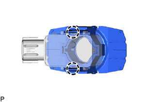
| (a) Engage the 2 claws to install a new front corner ultrasonic sensor retainer to the front corner ultrasonic sensor. |
|
(b) Clean the surface of the front bumper assembly.
(1) Remove any remaining double-sided tape from the front bumper assembly.
(2) Wipe off any adhesive residue with cleaner.
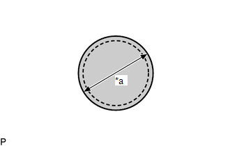
| (c) Cover the sensor installation hole with a 19 mm (0.748 in.) circular piece of tape. |
|
(d) Using a brush or felt, apply primer or equivalent to the front corner ultrasonic sensor retainer installation area.
NOTICE:
- Use a clean brush or felt.
- Do not touch the front bumper assembly until the primer has dried.
.png) | Primer |
(e) Confirm that the primer has completely dried by touching the front bumper assembly. Then remove the tape.
(f) Peel off the release paper from the front corner ultrasonic sensor retainer.
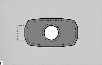
(g) Align the front corner ultrasonic sensor retainer with front corner ultrasonic sensor with the mark on the front bumper assembly and install it as shown in the illustration.
NOTICE:
- Ensure that the sensor tip is correctly inserted into the sensor installation hole of the front bumper assembly.
- Ensure that the front corner ultrasonic sensor retainer is within the scribed line.
- The double-sided tape of a front corner ultrasonic sensor retainer will deteriorate if it is detached. Make sure to replace the front corner ultrasonic sensor retainer with a new one when reattachment is necessary.
HINT:
Press the area shown in the illustration with a force of 30 N (3.0 kgf) for 3 seconds to securely install the front corner ultrasonic sensor retainer to the front bumper assembly. Confirm there is no clearance between the front corner ultrasonic sensor retainer and front bumper assembly.
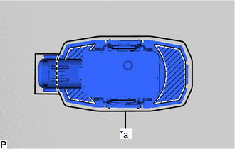
| *a | Scribed Line |
.png) | Press Here |
3. INSTALL FRONT CORNER ULTRASONIC SENSOR
HINT:
The illustration is for the LH side. The orientation for the RH side is the opposite of the LH side.
(a) When replacing only the front corner ultrasonic sensor:
(1) Engage the 2 claws to install the front corner ultrasonic sensor as shown in the illustration.
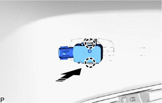
| | Install in this Direction |
(2) Connect the connector.
4. INSTALL FRONT CENTER ULTRASONIC SENSOR
HINT:
The illustration is for the LH side. The orientation for the RH side is the opposite of the LH side.
(a) Engage the 2 claws to install the front center ultrasonic sensor as shown in the illustration.
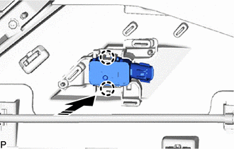
| | Install in this Direction |
(b) Connect the connector.
5. INSTALL FRONT BUMPER ASSEMBLY
Click here .gif)
6. PERFORM CALIBRATION
for HV Model: Click here
for Gasoline Model: Click here
SST: 09989-00020
READ NEXT:
 Removal
REMOVAL CAUTION / NOTICE / HINT The necessary procedures (adjustment, calibration, initialization, or registration) that must be performed after parts are removed and installed, or replaced during ult
Components
COMPONENTS ILLUSTRATION *1 REAR CENTER ULTRASONIC SENSOR *2 REAR CENTER ULTRASONIC SENSOR RETAINER *3 REAR CORNER ULTRASONIC SENSOR *4 REAR CORNER ULTRASONIC SENSOR RETAINER *5
SEE MORE:
Lubrication System
On-vehicle InspectionON-VEHICLE INSPECTION PROCEDURE 1. CHECK ENGINE OIL LEVEL (a) Connect the Techstream to the DLC3. (b) Turn the power switch on (IG). (c) Turn the Techstream on. (d) Put the engine in inspection Mode (Maintenance Mode). Powertrain > Hybrid Control > Utility Tester Displ
Turn Signal Switch Circuit
DESCRIPTION The steering sensor receives the turn signal switch information and controls the turn signal lights. WIRING DIAGRAM PROCEDURE 1. READ VALUE USING TECHSTREAM (a) Connect the Techstream to the DLC3. (b) Turn the engine switch on (IG). (c) Turn the Techstream on. (d) Enter the fol
