Lexus ES: Removal
REMOVAL
CAUTION / NOTICE / HINT
The necessary procedures (adjustment, calibration, initialization, or registration) that must be performed after parts are removed and installed, or replaced during ultrasonic sensor removal/installation are shown below.
Necessary Procedure After Parts Removed/Installed/Replaced (for HV Model)| Replaced Part or Performed Procedure | Necessary Procedure | Effect/Inoperative Function When Necessary Procedures are not Performed | Link |
|---|---|---|---|
| *: w/ Panoramic View Monitor System | |||
|
|
| |
| Front bumper assembly* | Front television camera view adjustment | Panoramic View Monitor System | |
| Replaced Part or Performed Procedure | Necessary Procedure | Effect/Inoperative Function When Necessary Procedures are not Performed | Link |
|---|---|---|---|
| *: w/ Panoramic View Monitor System | |||
|
|
| |
| Front bumper assembly* | Front television camera view adjustment | Panoramic View Monitor System | |
PROCEDURE
1. REMOVE FRONT BUMPER ASSEMBLY
Click here .gif)
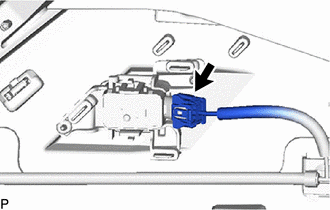
2. REMOVE FRONT CENTER ULTRASONIC SENSOR
HINT:
The illustration is for the LH side. The orientation for the RH side is the opposite of the LH side.
| (a) Disconnect the connector. |
|
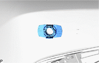
(b) Disengage the 2 claws and remove the front center ultrasonic sensor as shown in the illustration.
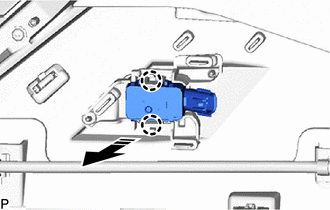
.png) | Remove in this Direction |
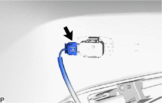
3. REMOVE FRONT CORNER ULTRASONIC SENSOR
HINT:
The illustration is for the LH side. The orientation for the RH side is the opposite of the LH side.
| (a) Disconnect the connector. |
|
(b) Disengage the 2 claws and remove the front corner ultrasonic sensor as shown in the illustration.
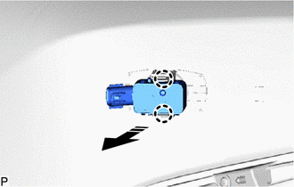
| | Remove in this Direction |
4. REMOVE FRONT CORNER ULTRASONIC SENSOR RETAINER
HINT:
- Perform this procedure only when replacement of the front corner ultrasonic sensor retainer is necessary.
- When removing the front corner ultrasonic sensor retainer, heat the front bumper assembly and front corner ultrasonic sensor retainer using a heat light.
- The illustration is for the LH side. Use the same procedure for the RH side and LH side.
(a) Heat the front bumper assembly and front corner ultrasonic sensor retainer using a heat light at the specified temperature for 3 to 5 minutes.
Heating Temperature:
| Item | Temperature |
|---|---|
| Front Bumper Assembly | 40 to 60°C (104 to 140°F) |
| Front Corner Ultrasonic Sensor Retainer |
CAUTION:
- Do not touch the heat light and heated parts.
- Touching the heat light may result in burns.
- Touching heated parts for a long time may result in burns.
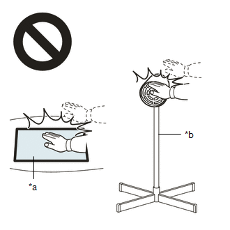
| *a | Heated Part |
| *b | Heat Light |
| (b) Remove the front corner ultrasonic sensor retainer. |
|
5. REMOVE ULTRASONIC SENSOR CUSHION SET
HINT:
Only perform this procedure when removing and installing the ultrasonic sensor cushion set.
(a) Remove the ultrasonic sensor cushion set as shown in the illustration.
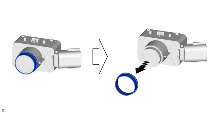
| | Remove in this Direction | - | - |
READ NEXT:
 Components
COMPONENTS ILLUSTRATION *1 REAR CENTER ULTRASONIC SENSOR *2 REAR CENTER ULTRASONIC SENSOR RETAINER *3 REAR CORNER ULTRASONIC SENSOR *4 REAR CORNER ULTRASONIC SENSOR RETAINER *5
Inspection
INSPECTION PROCEDURE 1. INSPECT REAR CENTER ULTRASONIC SENSOR (a) Measure the resistance according to the value(s) in the table below. Standard Resistance: Tester Connection Condition Speci
SEE MORE:
Removal
REMOVAL CAUTION / NOTICE / HINT The necessary procedures (adjustment, calibration, initialization or registration) that must be performed after parts are removed and installed, or replaced during windshield glass sub-assembly removal/installation are shown below. Necessary Procedure After Parts Remo
Inspection Mode Procedure
INSPECTION MODE PROCEDURE
INSPECTION MODE (for HV Model)
NOTICE:
When operating the vehicle in an inspection mode for an operation such as a speedometer
test, a DTC may be stored. Therefore, if the warning light illuminates, check for
DTCs using the Techstream and clear the DTCs.
HINT:
If t
