Lexus ES: Input / Output Signal Circuit
DESCRIPTION
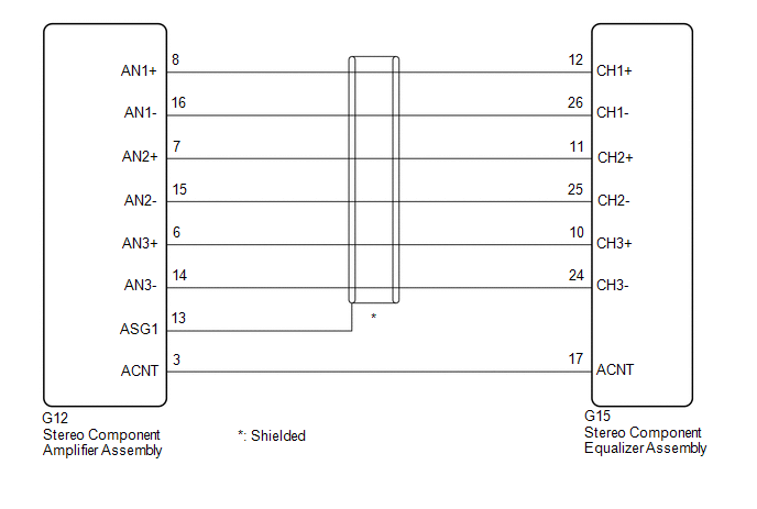
The stereo component equalizer assembly uses this circuit to send and receive signals to and from the stereo component amplifier assembly.
WIRING DIAGRAM
PROCEDURE
| 1. | CHECK HARNESS AND CONNECTOR (STEREO COMPONENT EQUALIZER ASSEMBLY - STEREO COMPONENT AMPLIFIER ASSEMBLY) |
(a) Disconnect the G15 stereo component equalizer assembly connector.
(b) Disconnect the G12 stereo component amplifier assembly connector.
(c) Measure the resistance according to the value(s) in the table below.
Standard Resistance:
| Tester Connection | Condition | Specified Condition |
|---|---|---|
| G15-12 (CH1+) - G12-8 (AN1+) | Always | Below 1 Ω |
| G15-26 (CH1-) - G12-16 (AN1-) | Always | Below 1 Ω |
| G15-11 (CH2+) - G12-7 (AN2+) | Always | Below 1 Ω |
| G15-25 (CH2-) - G12-15 (AN2-) | Always | Below 1 Ω |
| G15-10 (CH3+) - G12-6 (AN3+) | Always | Below 1 Ω |
| G15-24 (CH3-) - G12-14 (AN3-) | Always | Below 1 Ω |
| G15-17 (ACNT) - G12-3 (ACNT) | Always | Below 1 Ω |
| G15-12 (CH1+) or G12-8 (AN1+) - Body ground | Always | 10 kΩ or higher |
| G15-26 (CH1-) or G12-16 (AN1-) - Body ground | Always | 10 kΩ or higher |
| G15-11 (CH2+) or G12-7 (AN2+) - Body ground | Always | 10 kΩ or higher |
| G15-25 (CH2-) or G12-15 (AN2-) - Body ground | Always | 10 kΩ or higher |
| G15-10 (CH3+) or G12-6 (AN3+) - Body ground | Always | 10 kΩ or higher |
| G15-24 (CH3-) or G12-14 (AN3-) - Body ground | Always | 10 kΩ or higher |
| G15-17 (ACNT) or G12-3 (ACNT) - Body ground | Always | 10 kΩ or higher |
| G12-13 (ASG1) - Body ground | Always | 10 kΩ or higher |
| OK | .gif) | PROCEED TO NEXT SUSPECTED AREA SHOWN IN PROBLEM SYMPTOMS TABLE |
| NG | | REPAIR OR REPLACE HARNESS OR CONNECTOR |
READ NEXT:
 Crankshaft Position Sensor "A" No Signal (P033531)
DESCRIPTION This DTC is output when a malfunction has occurred in the engine pulse signal system from the ECM. DTC No. Detection Item DTC Detection Condition Trouble Area P033531 Cranks
Parts Location
PARTS LOCATION ILLUSTRATION *1 ECM *2 INSTRUMENT PANEL JUNCTION BLOCK ASSEMBLY - ECU-B NO. 2 FUSE - ECU-IG1 NO. 4 FUSE - ECU-ACC FUSE *3 DLC3 *4 STEREO COMPONENT EQUALIZER ASSEMBLY
Power Source Circuit
DESCRIPTION This circuit is the power source circuit for the stereo component equalizer assembly. WIRING DIAGRAM CAUTION / NOTICE / HINT NOTICE: Inspect the fuses and relays for circuits related to t
SEE MORE:
Hybrid/EV Battery "A" Voltage Sensor Voltage Out of Range (P0B231C)
DTC SUMMARY MALFUNCTION DESCRIPTION The hybrid vehicle control ECU detects a VB sensor malfunction. The cause of this malfunction may be one of the following: Battery voltage sensor VB sensor internal circuit malfunction
Battery voltage sensor malfunction
Communication (wire harness) malfunctio
On-vehicle Inspection
ON-VEHICLE INSPECTION PROCEDURE 1. INSPECT STOP LIGHT SWITCH ASSEMBLY (a) Disconnect the A80 stop light switch assembly connector. *a Front view of wire harness connector (to Stop Light Switch Assembly) (b) Measure the voltage and resistance on the wire harness side connec
