Lexus ES: Illumination for Panel Switch does not Come on with Tail Switch ON
Lexus ES (XZ10) Service Manual / Audio & Visual & Telematics / Navigation / Multi Info Display / Navigation System (for Hv Model) / Illumination for Panel Switch does not Come on with Tail Switch ON
CAUTION / NOTICE / HINT
NOTICE:
-
Depending on the parts that are replaced during vehicle inspection or maintenance, performing initialization, registration or calibration may be needed. Refer to Precaution for Navigation System.
Click here
.gif)
-
When replacing the radio receiver assembly, always replace it with a new one. If a radio receiver assembly which was installed to another vehicle is used, the following may occur:
- A communication malfunction DTC may be stored.
- The radio receiver assembly may not operate normally.
PROCEDURE
| 1. | CHECK VEHICLE SIGNAL (OPERATION CHECK) |
| (a) Enter the "Vehicle Signal Check Mode" screen. Refer to Check Vehicle Signal in Operation Check. Click here |
|
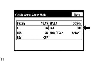
(b) Check that the display changes between ON and OFF according to the light control switch operation.
OK:
| Light Control Switch | Display |
|---|---|
| Tail or head | ON |
| Off or AUTO | OFF |
HINT:
- This display is updated once per second. As a result, it is normal for the display to lag behind the actual switch operation.
- Make sure to move the vehicle to a bright area before performing an operation check with the light control switch in the AUTO position.
| OK |  | REPLACE RADIO RECEIVER ASSEMBLY |
| NG | | PROCEED TO NEXT SUSPECTED AREA SHOWN IN PROBLEM SYMPTOMS TABLE |
READ NEXT:
 Microphone Circuit
DESCRIPTION
The radio receiver assembly and telephone microphone assembly are connected to each other using the microphone connection detection signal lines.
Using this circuit, the radio receive
Mute Signal Circuit between Stereo Component Amplifier and Telematics Transceiver
DESCRIPTION The DCM (telematics transceiver) sends a mute signal to the stereo component amplifier assembly. The stereo component amplifier assembly controls the volume according to the mute signal fr
No Sound can be Heard from Speakers
PROCEDURE 1. CHECK AUDIO SETTINGS (a) In sound output setting mode, set volume, fader and balance to the initial values and check that the sound is normal. OK: Audio system returns to normal
SEE MORE:
Software Incompatibility with Brake System Control Module Not Programmed (U031851)
DESCRIPTION If the forward recognition camera cannot verify the vehicle information sent from the skid control ECU (brake booster with master cylinder assembly), the forward recognition camera stores DTC U031851. DTC No. Detection Item DTC Detection Condition Trouble Area MIL DTC Output
Parking Assist ECU Communication Stop Mode
DESCRIPTION Detection Item Symptom Trouble Area Parking Assist ECU Communication Stop Mode Any of the following conditions are met:
Communication stop for "Panoramic View Monitor / Circumference Monitoring Camera Control Module" is indicated on the "Communication Bus Check" screen of
© 2016-2026 Copyright www.lexguide.net
