Lexus ES: Microphone Circuit
DESCRIPTION
- The radio receiver assembly and telephone microphone assembly are connected to each other using the microphone connection detection signal lines.
- Using this circuit, the radio receiver assembly sends power to the telephone microphone assembly, and the telephone microphone assembly sends microphone signals to the radio receiver assembly and navigation ECU.*1
-
Using this circuit, the DCM (telematics transceiver) sends power to the telephone microphone assembly, and the telephone microphone assembly sends microphone signals to the radio receiver assembly and navigation ECU via the DCM (telematics transceiver).*2
-
*1: w/o Manual (SOS) Switch
*2: w/ Manual (SOS) Switch
-
*1: w/o Manual (SOS) Switch
WIRING DIAGRAM
w/o Manual (SOS) Switch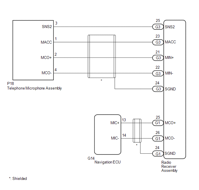 w/ Manual (SOS) Switch
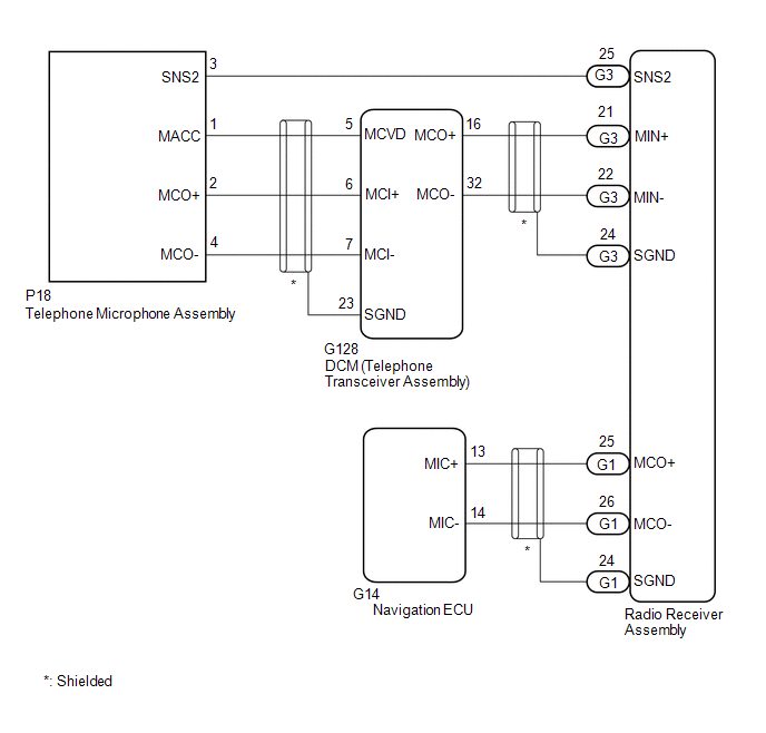
CAUTION / NOTICE / HINT
NOTICE:
-
Depending on the parts that are replaced during vehicle inspection or maintenance, performing initialization, registration or calibration may be needed. Refer to Precaution for Navigation System.
Click here
.gif)
-
When replacing the radio receiver assembly, always replace it with a new one. If a radio receiver assembly which was installed to another vehicle is used, the following may occur:
- A communication malfunction DTC may be stored.
- The radio receiver assembly may not operate normally.
-
Before replacing the DCM (telematics transceiver), refer to Registration.
Click here
PROCEDURE
| 1. | CHECK MICROPHONE AND VOICE RECOGNITION (INPUT TO NAVIGATION ECU) |
| (a) Enter the "Microphone Check" screen. Refer to Check Microphone (Input to navigation ECU) in Operation Check. Click here |
|
.png)
(b) When voice is input into the microphone, check that the microphone input level meter changes according to the input voice.
OK:
Check results are normal.
| OK | .gif) | PROCEED TO NEXT SUSPECTED AREA SHOWN IN PROBLEM SYMPTOMS TABLE |
|
.gif)
| 2. | CHECK MICROPHONE AND VOICE RECOGNITION (INPUT TO RADIO RECEIVER ASSEMBLY) |
| (a) Enter the "Microphone Check" screen. Refer to Check Microphone (Input to radio receiver assembly) in Operation Check. Click here |
|
(b) When voice is input into the microphone, check that the microphone input level meter changes according to the input voice.
OK:
Check results are normal.
| NG | | GO TO STEP 5 |
|
| 3. | CHECK HARNESS AND CONNECTOR (RADIO RECEIVER ASSEMBLY - NAVIGATION ECU) |
(a) Disconnect the G1 radio receiver assembly connector.
(b) Disconnect the G14 navigation ECU connector.
(c) Measure the resistance according to the value(s) in the table below.
Standard Resistance:
| Tester Connection | Condition | Specified Condition |
|---|---|---|
| G1-25 (MCO+) - G14-13 (MIC+) | Always | Below 1 Ω |
| G1-26 (MCO-) - G14-14 (MIC-) | Always | Below 1 Ω |
| G1-25 (MCO+) or G14-13 (MIC+) - Body ground | Always | 10 kΩ or higher |
| G1-26 (MCO-) or G14-14 (MIC-) - Body ground | Always | 10 kΩ or higher |
| G1-24 (SGND) - Body ground | Always | 10 kΩ or higher |
| NG | | REPAIR OR REPLACE HARNESS OR CONNECTOR |
|
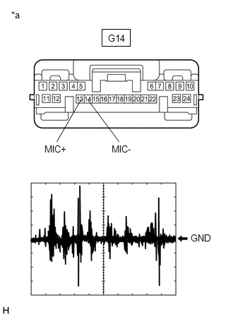
| 4. | INSPECT RADIO RECEIVER ASSEMBLY (OUTPUT TO NAVIGATION ECU) |
(a) Disconnect the G14 navigation ECU connector.
(b) Turn the power switch on (ACC).
| (c) Check the signal waveform according to the condition(s) in the table below.
OK: The waveform is similar to that shown in the illustration. HINT: The oscilloscope waveform shown in the illustration is an example for reference only. |
|
| OK | | PROCEED TO NEXT SUSPECTED AREA SHOWN IN PROBLEM SYMPTOMS TABLE |
| NG | | REPLACE RADIO RECEIVER ASSEMBLY |
| 5. | CHECK MODEL |
(a) Check the model to be inspected.
| Result | Proceed to |
|---|---|
| w/ Manual (SOS) Switch | A |
| w/o Manual (SOS) Switch | B |
| B | | GO TO STEP 12 |
|
| 6. | CHECK HARNESS AND CONNECTOR (RADIO RECEIVER ASSEMBLY - TELEPHONE MICROPHONE ASSEMBLY) |
(a) Disconnect the G3 radio receiver assembly connector.
(b) Disconnect the P18 telephone microphone assembly connector.
(c) Measure the resistance according to the value(s) in the table below.
Standard Resistance:
| Tester Connection | Condition | Specified Condition |
|---|---|---|
| G3-25 (SNS2) - P18-3 (SNS2) | Always | Below 1 Ω |
| G3-25 (SNS2) or P18-3 (SNS2) - Body ground | Always | 10 kΩ or higher |
| NG | | REPAIR OR REPLACE HARNESS OR CONNECTOR |
|
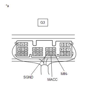
| 7. | CHECK HARNESS AND CONNECTOR (RADIO RECEIVER ASSEMBLY - DCM (TELEMATICS TRANSCEIVER)) |
(a) Disconnect the G3 radio receiver assembly connector.
(b) Disconnect the G128 DCM (telematics transceiver) connector.
(c) Measure the resistance according to the value(s) in the table below.
Standard Resistance:
| Tester Connection | Condition | Specified Condition |
|---|---|---|
| G3-21 (MIN+) - G128-16 (MCO+) | Always | Below 1 Ω |
| G3-22 (MIN-) - G128-32 (MCO-) | Always | Below 1 Ω |
| G3-21 (MIN+) or G128-16 (MCO+) - Body ground | Always | 10 kΩ or higher |
| G3-22 (MIN-) or G128-32 (MCO-) - Body ground | Always | 10 kΩ or higher |
| G3-24 (SGND) - Body ground | Always | 10 kΩ or higher |
| NG | | REPAIR OR REPLACE HARNESS OR CONNECTOR |
|
| 8. | CHECK HARNESS AND CONNECTOR (DCM (TELEMATICS TRANSCEIVER) - TELEPHONE MICROPHONE ASSEMBLY) |
(a) Disconnect the G128 DCM (telematics transceiver) connector.
(b) Disconnect the P18 telephone microphone assembly connector.
(c) Measure the resistance according to the value(s) in the table below.
Standard Resistance:
| Tester Connection | Condition | Specified Condition |
|---|---|---|
| G128-5 (MCVD) - P18-1 (MACC) | Always | Below 1 Ω |
| G128-6 (MCI+) - P18-2 (MCO+) | Always | Below 1 Ω |
| G128-7 (MCI-) - P18-4 (MCO-) | Always | Below 1 Ω |
| G128-5 (MCVD) or P18-1 (MACC) - Body ground | Always | 10 kΩ or higher |
| G128-6 (MCI+) or P18-2 (MCO+) - Body ground | Always | 10 kΩ or higher |
| G128-7 (MCI-) or P18-4 (MCO-) - Body ground | Always | 10 kΩ or higher |
| G128-23 (SGND) - Body ground | Always | 10 kΩ or higher |
| NG | | REPAIR OR REPLACE HARNESS OR CONNECTOR |
|
| 9. | CHECK DCM (TELEMATICS TRANSCEIVER) |
| (a) Remove the DCM (telematics transceiver) with the connector(s) still connected. |
|
(b) Measure the voltage according to the value(s) in the table below.
Standard Voltage:
| Tester Connection | Condition | Specified Condition |
|---|---|---|
| G128-5 (MCVD) - Body ground | Power switch on (ACC) | 4 to 6 V |
(c) Measure the resistance according to the value(s) in the table below.
Standard Resistance:
| Tester Connection | Condition | Specified Condition |
|---|---|---|
| G128-23 (SGND) - Body ground | Always | Below 1 Ω |
| G128-7 (MCI-) - Body ground | Always | Below 1 Ω |
| NG | | REPLACE DCM (TELEMATICS TRANSCEIVER) |
|
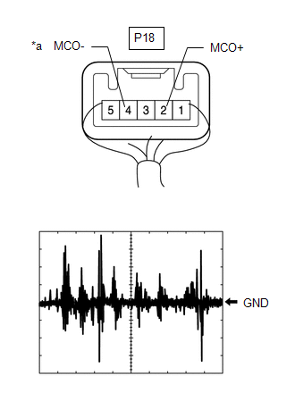
| 10. | CHECK TELEPHONE MICROPHONE ASSEMBLY (OUTPUT TO DCM (TELEMATICS TRANSCEIVER)) |

| *a | Component with harness connected (Telephone Microphone Assembly) |
(a) Check the output waveform.
(1) Remove the telephone microphone assembly with the connector(s) still connected.
Click here
(2) Connect an oscilloscope to terminal P18-2 (MCO+) and P18-4 (MCO-).
(3) Turn the power switch on (ACC).
(4) Sound is input to the telephone microphone assembly when the user is closer than 125 mm from the telephone microphone assembly sound holes in the roof headlining holder cover.
(5) Check the signal waveform according to the condition(s) in the table below.
| Item | Condition |
|---|---|
| Measurement terminal | P18-2 (MCO+) - P18-4 (MCO-) |
| Tool setting | 50 mV/DIV., 500 ms/DIV. |
| Vehicle condition |
|
OK:
The waveform is similar to that shown in the illustration.
HINT:
The oscilloscope waveform shown in the illustration is an example for reference only.
| NG | | REPLACE TELEPHONE MICROPHONE ASSEMBLY |
|
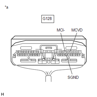
| 11. | CHECK DCM (TELEMATICS TRANSCEIVER) (OUTPUT TO RADIO RECEIVER ASSEMBLY) |
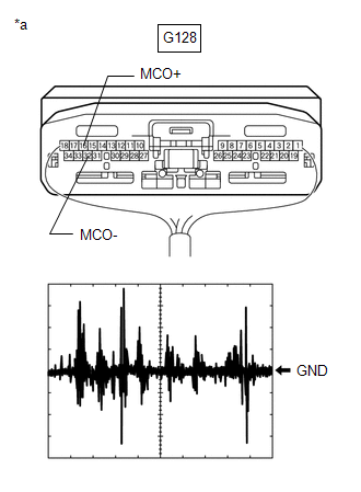
| *a | Component with harness connected (DCM (Telematics Transceiver)) |
(a) Check the output waveform.
(1) Remove the DCM (telematics transceiver) with the connector(s) still connected.
Click here
(2) Connect an oscilloscope to terminal G128-16 (MCO+) and G128-32 (MCO-).
(3) Turn the power switch on (ACC).
(4) Sound is input to the telephone microphone assembly when the user is closer than 125 mm from the telephone microphone assembly sound holes in the roof headlining holder cover.
(5) Check the signal waveform according to the condition(s) in the table below.
| Item | Condition |
|---|---|
| Measurement terminal | G128-16 (MCO+) - G128-32 (MCO-) |
| Tool setting | 50 mV/DIV., 500 ms/DIV. |
| Vehicle condition |
|
OK:
The waveform is similar to that shown in the illustration.
HINT:
The oscilloscope waveform shown in the illustration is an example for reference only.
| OK | | REPLACE RADIO RECEIVER ASSEMBLY |
| NG | | REPLACE DCM (TELEMATICS TRANSCEIVER) |
| 12. | CHECK HARNESS AND CONNECTOR (RADIO RECEIVER ASSEMBLY - TELEPHONE MICROPHONE ASSEMBLY) |
(a) Disconnect the G3 radio receiver assembly connector.
(b) Disconnect the P18 telephone microphone assembly connector.
(c) Measure the resistance according to the value(s) in the table below.
Standard Resistance:
| Tester Connection | Condition | Specified Condition |
|---|---|---|
| G3-25 (SNS2) - P18-3 (SNS2) | Always | Below 1 Ω |
| G3-23 (MACC) - P18-1 (MACC) | Always | Below 1 Ω |
| G3-21 (MIN+) - P18-2 (MCO+) | Always | Below 1 Ω |
| G3-22 (MIN-) - P18-4 (MCO-) | Always | Below 1 Ω |
| G3-25 (SNS2) or P18-3 (SNS2) - Body ground | Always | 10 kΩ or higher |
| G3-23 (MACC) or P18-1 (MACC) - Body ground | Always | 10 kΩ or higher |
| G3-21 (MIN+) or P18-2 (MCO+) - Body ground | Always | 10 kΩ or higher |
| G3-22 (MIN-) or P18-4 (MCO-) - Body ground | Always | 10 kΩ or higher |
| G3-24 (SGND) - Body ground | Always | 10 kΩ or higher |
| NG | | REPAIR OR REPLACE HARNESS OR CONNECTOR |
|
| 13. | CHECK RADIO RECEIVER ASSEMBLY |
| (a) Remove the radio receiver assembly with the connector(s) still connected. |
|
(b) Measure the voltage according to the value(s) in the table below.
Standard Voltage:
| Tester Connection | Condition | Specified Condition |
|---|---|---|
| G3-23 (MACC) - Body ground | Power switch on (ACC) | 4 to 6 V |
(c) Measure the resistance according to the value(s) in the table below.
Standard Resistance:
| Tester Connection | Condition | Specified Condition |
|---|---|---|
| G3-22 (MIN-) - Body ground | Always | Below 1 Ω |
| G3-24 (SGND) - Body ground | Always | Below 1 Ω |
| NG | | REPLACE RADIO RECEIVER ASSEMBLY |
|
| 14. | CHECK TELEPHONE MICROPHONE ASSEMBLY (OUTPUT TO RADIO RECEIVER ASSEMBLY) |
| *a | Component with harness connected (Telephone Microphone Assembly) |
(a) Check the output waveform.
(1) Remove the telephone microphone assembly with the connector(s) still connected.
Click here
(2) Connect an oscilloscope to terminal P18-2 (MCO+) and P18-4 (MCO-).
(3) Turn the power switch on (ACC).
(4) Sound is input to the telephone microphone assembly when the user is closer than 125 mm from the telephone microphone assembly sound holes in the roof headlining holder cover.
(5) Check the signal waveform according to the condition(s) in the table below.
| Item | Condition |
|---|---|
| Measurement terminal | P18-2 (MCO+) - P18-4 (MCO-) |
| Tool setting | 50 mV/DIV., 500 ms/DIV. |
| Vehicle condition |
|
OK:
The waveform is similar to that shown in the illustration.
HINT:
The oscilloscope waveform shown in the illustration is an example for reference only.
| OK | | REPLACE RADIO RECEIVER ASSEMBLY |
| NG | | REPLACE TELEPHONE MICROPHONE ASSEMBLY |
READ NEXT:
 Mute Signal Circuit between Stereo Component Amplifier and Telematics Transceiver
DESCRIPTION The DCM (telematics transceiver) sends a mute signal to the stereo component amplifier assembly. The stereo component amplifier assembly controls the volume according to the mute signal fr
No Sound can be Heard from Speakers
PROCEDURE 1. CHECK AUDIO SETTINGS (a) In sound output setting mode, set volume, fader and balance to the initial values and check that the sound is normal. OK: Audio system returns to normal
Noise Occurs or Sound Skips when Portable Player Plays
CAUTION / NOTICE / HINT HINT:
Perform this check with the portable player volume set at an appropriate level.
Make sure that there are no obstructions between the portable player and the radio re
SEE MORE:
Navigation Processor Malfunction (B15AD)
DESCRIPTION This DTC is stored when a malfunction occurs in the navigation ECU. DTC No. Detection Item DTC Detection Condition Trouble Area B15AD Navigation Processor Malfunction When either condition below is met:
A short to ground, short to +B or open occurs in the gyro signal
Roof Drip Side Finish Moulding
ComponentsCOMPONENTS ILLUSTRATION *1 CENTER ROOF DRIP SIDE FINISH MOULDING *2 NO. 1 ROOF DRIP SIDE FINISH MOULDING CLIP ● Non-reusable part - - RemovalREMOVAL CAUTION / NOTICE / HINT HINT:
Use the same procedure for the RH side and LH side.
The following procedure is
