Lexus ES: Illumination Circuit
DESCRIPTION
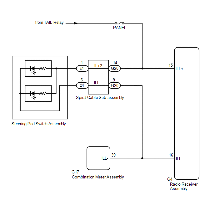
Power is supplied to the radio receiver assembly and steering pad switch assembly illumination when the light control switch is in the tail or head position.
WIRING DIAGRAM
CAUTION / NOTICE / HINT
NOTICE:
-
The vehicle is equipped with a Supplemental Restraint System (SRS) which includes components such as airbags. Before servicing (including removal or installation of parts), be sure to read the precaution for Supplemental Restraint System.
Click here
.gif)
- Inspect the fuses for circuits related to this system before performing the following procedure.
PROCEDURE
| 1. | CHECK ILLUMINATION |
(a) Check if the illumination for the radio receiver assembly, steering pad switch assembly, heater control switch or others (hazard switch, transmission control switch, etc.) comes on when the light control switch is turned to the head or tail position.
| Result | Proceed to |
|---|---|
| Illumination comes on for all components except steering pad switch assembly. | A |
| Illumination comes on for all components except radio receiver assembly. | B |
| No illumination comes on (radio receiver assembly, hazard switch, heater control switch, etc.). | C |
| B | .gif) | GO TO STEP 5 |
| C | | GO TO LIGHTING SYSTEM |
|
.gif)
| 2. | CHECK HARNESS AND CONNECTOR (ILLUMINATION SIGNAL) |
(a) Disconnect the G20 spiral cable sub-assembly connector.
(b) Measure the voltage according to the value(s) in the table below.
Standard Voltage:
| Tester Connection | Condition | Specified Condition |
|---|---|---|
| G20-14 (IL+2) - Body ground | Power switch off Light control switch in tail or head position | 11 to 14 V |
| NG | | REPAIR OR REPLACE HARNESS OR CONNECTOR |
|
| 3. | INSPECT STEERING PAD SWITCH ASSEMBLY |
(a) Remove the steering pad switch assembly.
Click here
(b) Inspect the steering pad switch assembly.
Click here
| NG | | REPLACE STEERING PAD SWITCH ASSEMBLY |
|
| 4. | INSPECT SPIRAL CABLE SUB-ASSEMBLY |
(a) Remove the spiral cable sub-assembly.
Click here
(b) Inspect the spiral cable sub-assembly.
Click here
| OK | | REPAIR OR REPLACE HARNESS OR CONNECTOR (SPIRAL CABLE SUB-ASSEMBLY - RADIO RECEIVER ASSEMBLY, COMBINATION METER ASSEMBLY) |
| NG | | REPLACE SPIRAL CABLE SUB-ASSEMBLY |
| 5. | CHECK HARNESS AND CONNECTOR (ILLUMINATION SIGNAL) |
(a) Disconnect the G4 radio receiver assembly connector.
(b) Measure the voltage according to the value(s) in the table below.
Standard Voltage:
| Tester Connection | Condition | Specified Condition |
|---|---|---|
| G4-15 (ILL+) - Body ground | Power switch off Light control switch in tail or head position | 11 to 14 V |
| NG | | REPAIR OR REPLACE HARNESS OR CONNECTOR |
|
| 6. | CHECK HARNESS AND CONNECTOR (RADIO RECEIVER ASSEMBLY - COMBINATION METER ASSEMBLY) |
(a) Disconnect the G4 radio receiver assembly connector.
(b) Disconnect the G17 combination meter assembly connector.
(c) Measure the resistance according to the value(s) in the table below.
Standard Resistance:
| Tester Connection | Condition | Specified Condition |
|---|---|---|
| G4-16 (ILL-) - G17-39 (ILL-) | Always | Below 1 Ω |
| G4-16 (ILL-) or G17-39 (ILL-) - Body ground | Always | 10 kΩ or higher |
| OK | | PROCEED TO NEXT SUSPECTED AREA SHOWN IN PROBLEM SYMPTOMS TABLE |
| NG | | REPAIR OR REPLACE HARNESS OR CONNECTOR |
READ NEXT:
 Illumination for Panel Switch does not Come on with Tail Switch ON
CAUTION / NOTICE / HINT NOTICE:
Depending on the parts that are replaced during vehicle inspection or maintenance, performing initialization, registration or calibration may be needed. Refer to Pre
Microphone Circuit
DESCRIPTION
The radio receiver assembly and telephone microphone assembly are connected to each other using the microphone connection detection signal lines.
Using this circuit, the radio receive
Mute Signal Circuit between Radio Receiver and Stereo Component Amplifier
DESCRIPTION This circuit sends a signal to the stereo component amplifier assembly to mute noise. Due to this, the noise produced by changing the sound source ceases. If there is an open in the circui
SEE MORE:
Throttle Actuator "A" Control Throttle Body Range/Performance (P211900,P211904,P211977,P21199B)
DESCRIPTION The electronic throttle control system is composed of the throttle actuator, throttle position sensor, and ECM. The ECM operates the throttle actuator to regulate the throttle valve in response to a request from the hybrid system. The throttle position sensor detects the opening angle of
Inspection
INSPECTION PROCEDURE 1. INSPECT MASS AIR FLOW METER SUB-ASSEMBLY (a) Perform a visual check for any foreign matter on the intake air temperature sensor (thermistor) of the mass air flow meter sub-assembly shown in the illustration. OK: There is no foreign matter. If the result is not as specifie
