Lexus ES: Horn
Components
COMPONENTS
ILLUSTRATION
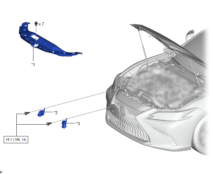
| *1 | COOL AIR INTAKE DUCT SEAL | *2 | HIGH PITCHED HORN ASSEMBLY |
| *3 | LOW PITCHED HORN ASSEMBLY | - | - |
.png) | N*m (kgf*cm, ft.*lbf): Specified torque | - | - |
Removal
REMOVAL
PROCEDURE
1. REMOVE COOL AIR INTAKE DUCT SEAL
Click here .gif)
2. REMOVE HIGH PITCHED HORN ASSEMBLY
| (a) Remove the bolt. |
|
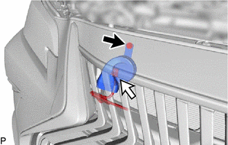
(b) Disconnect the connector to remove the high pitched horn assembly.
3. REMOVE LOW PITCHED HORN ASSEMBLY
| (a) Remove the bolt. |
|
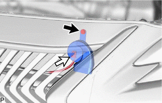
(b) Disconnect the connector to remove the low pitched horn assembly.
Inspection
INSPECTION
PROCEDURE
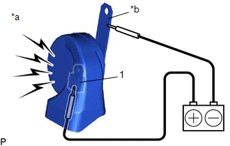
1. INSPECT HIGH PITCHED HORN ASSEMBLY
| (a) Apply auxiliary battery voltage and check the operation of the high pitched horn assembly according to the table below. OK:
If the result is not as specified, replace the high pitched horn assembly. |
|
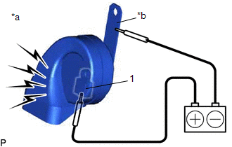
2. INSPECT LOW PITCHED HORN ASSEMBLY
| (a) Apply auxiliary battery voltage and check the operation of the low pitched horn assembly according to the table below. OK:
If the result is not as specified, replace the low pitched horn assembly. |
|
Installation
INSTALLATION
PROCEDURE
1. INSTALL LOW PITCHED HORN ASSEMBLY
(a) Connect the connector.
(b) Install the low pitched horn assembly with the bolt.
Torque:
19.1 N·m {195 kgf·cm, 14 ft·lbf}
2. INSTALL HIGH PITCHED HORN ASSEMBLY
(a) Connect the connector.
(b) Install the high pitched horn assembly with the bolt.
Torque:
19.1 N·m {195 kgf·cm, 14 ft·lbf}
3. INSTALL COOL AIR INTAKE DUCT SEAL
Click here .gif)
READ NEXT:
 Parts Location
PARTS LOCATION ILLUSTRATION *A for Type A *B for Type B *1 HIGH PITCHED HORN ASSEMBLY *2 LOW PITCHED HORN ASSEMBLY *3 HORN RELAY *4 ENGINE ROOM RELAY BLOCK AND JUNCTION B
Precaution
PRECAUTION PRECAUTION FOR DISCONNECTING CABLE FROM NEGATIVE AUXILIARY BATTERY TERMINAL NOTICE: When disconnecting the cable from the negative (-) auxiliary battery terminal, initialize the following s
SEE MORE:
If your vehicle overheats
The following may indicate that
your vehicle is overheating.
The engine coolant temperature
gauge is in the red zone
or a loss of hybrid system power is
experienced. (For example, the
vehicle speed does not increase.)
"Engine Coolant Temp High Stop
in a Safe Place See Owner's
Manu
Problem Symptoms Table
PROBLEM SYMPTOMS TABLE NOTICE:
If the battery voltage becomes low, battery load control will operate in order to ensure sufficient power is supplied to the power steering system. In this case, the windshield deicer system may not operate.
HINT:
Use the table below to help determine the caus
