Lexus ES: Headlight Dimmer Switch Circuit
DESCRIPTION
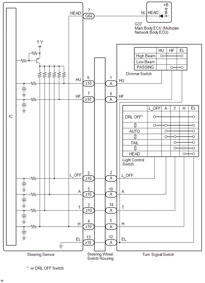
The steering sensor receives the following switch information:
- Light control switch in DRL OFF*, tail, head or AUTO position
-
Dimmer switch in high, low or high flash (pass) position
- *: w/ DRL OFF Switch
WIRING DIAGRAM
CAUTION / NOTICE / HINT
NOTICE:
Before replacing the main body ECU (multiplex network body ECU), refer to Registration.
Click here .gif)
PROCEDURE
| 1. | READ VALUE USING TECHSTREAM |
(a) Connect the Techstream to the DLC3.
(b) Turn the engine switch on (IG).
(c) Turn the Techstream on.
(d) Enter the following menus: Chassis / Steering Angle Sensor / Data List.
(e) Read the Data List according to the display on the Techstream.
Chassis > Steering Angle Sensor > Data List| Tester Display | Measurement Item | Range | Normal Condition | Diagnostic Note |
|---|---|---|---|---|
| Light OFF Switch | Light control switch DRL OFF position signal | OFF or ON | OFF: Light control switch not in DRL OFF position ON: Light control switch in DRL OFF position | w/ DRL OFF Switch |
| Auto Light Switch | Light control switch AUTO position signal | OFF or ON | OFF: Light control switch not in AUTO position ON: Light control switch in AUTO position | - |
| Head Light Switch (Tail) | Light control switch tail position signal | OFF or ON | OFF: Light control switch in neither tail nor head position ON: Light control switch in tail or head position | - |
| Head Light Switch (Head) | Light control switch head position signal | OFF or ON | OFF: Light control switch not in head position ON: Light control switch in head position | - |
| High Beam Main Switch | Dimmer switch high position signal | OFF or ON | OFF: Dimmer switch not in high position ON: Dimmer switch in high position | - |
| Passing Light Switch | Dimmer switch high flash position (pass) signal | OFF or ON | OFF: Dimmer switch not in high flash position ON: Dimmer switch in high flash position | - |
| Tester Display |
|---|
| Light OFF Switch |
| Auto Light Switch |
| Head Light Switch (Tail) |
| Head Light Switch (Head) |
| High Beam Main Switch |
| Passing Light Switch |
OK:
Normal conditions listed above are displayed.
| NG | .gif) | GO TO STEP 5 |
|
.gif)
| 2. | READ VALUE USING TECHSTREAM |
(a) Connect the Techstream to the DLC3.
(b) Turn the engine switch on (IG).
(c) Turn the Techstream on.
(d) Enter the following menus: Body Electrical / Main Body / Data List.
(e) Read the Data List according to the display on the Techstream.
Body Electrical > Main Body > Data List| Tester Display | Measurement Item | Range | Normal Condition | Diagnostic Note |
|---|---|---|---|---|
| Head Light SW (Head) | Light control switch head position signal | OFF or ON | OFF: Light control switch not in head position ON: Light control switch in head position | - |
| Tester Display |
|---|
| Head Light SW (Head) |
OK:
Normal conditions listed above are displayed.
| OK | | PROCEED TO NEXT SUSPECTED AREA SHOWN IN PROBLEM SYMPTOMS TABLE |
|
| 3. | INSPECT STEERING SENSOR |
.png)
| *a | Component without harness connected (Steering Sensor) | - | - |
(a) Remove the steering sensor.
Click here
(b) Measure the resistance according to the value(s) in the table below.
Standard Resistance:
| Tester Connection | Condition | Specified Condition |
|---|---|---|
| G62-7 (HEAD) - z10-4 (H) | Always | Below 1 Ω |
| NG | | REPLACE STEERING SENSOR |
|
| 4. | CHECK HARNESS AND CONNECTOR (STEERING SENSOR - MAIN BODY ECU (MULTIPLEX NETWORK BODY ECU)) |
(a) Disconnect the G37 main body ECU (multiplex network body ECU) connector.
(b) Measure the resistance according to the value(s) in the table below.
Standard Resistance:
| Tester Connection | Condition | Specified Condition |
|---|---|---|
| G62-7 (HEAD) - G37-16 (HEAD) | Always | Below 1 Ω |
| G62-7 (HEAD) or G37-16 (HEAD) - Body ground | Always | 10 kΩ or higher |
| OK | | REPLACE MAIN BODY ECU (MULTIPLEX NETWORK BODY ECU) |
| NG | | REPAIR OR REPLACE HARNESS OR CONNECTOR |
| 5. | INSPECT TURN SIGNAL SWITCH |
(a) Remove the turn signal switch.
Click here
(b) Inspect the turn signal switch.
Click here
| NG | | REPLACE TURN SIGNAL SWITCH |
|
| 6. | INSPECT STEERING WHEEL SWITCH HOUSING |
(a) Remove the steering wheel switch housing.
Click here
(b) Inspect the steering wheel switch housing.
Click here
| OK | | REPLACE STEERING SENSOR |
| NG | | REPLACE STEERING WHEEL SWITCH HOUSING |
READ NEXT:
 Parking Light/Daytime Running Light Circuit
DESCRIPTION Parking light function:
When the main body ECU (multiplex network body ECU) receives the light control switch position signal, it sends an illumination request signal to the headlight E
Hazard Warning Switch Circuit
DESCRIPTION The combination meter assembly receives the hazard warning signal switch assembly on signal and controls the operation of the hazard warning lights. WIRING DIAGRAM CAUTION / NOTICE / HINT
Outside Handle Foot Light Circuit
DESCRIPTION The main body ECU (multiplex network body ECU) controls the outside handle foot lights. WIRING DIAGRAM CAUTION / NOTICE / HINT NOTICE: Before replacing the main body ECU (multiplex networ
SEE MORE:
If a warning light turns on or a
warning buzzer sounds
Calmly perform the following actions if any of the warning lights comes
on or
flashes. If a light comes on or flashes, but then goes off, this does not
necessarily
indicate a malfunction in the system. However, if this continues to occur,
have the vehicle inspected by your Lexus dealer.
Acti
Front Right Sensor Malfunction (C1AE4)
DESCRIPTION The front corner ultrasonic sensor RH is installed to the front bumper. The clearance warning ECU assembly detects obstacles based on signals received from the front corner ultrasonic sensor RH. If the front corner ultrasonic sensor RH has an open circuit or other malfunction, it will no
