Lexus ES: FR Damping Force Control Actuator Circuit (C1731-C1734)
DESCRIPTION
The absorber control actuator changes the damping force depending on absorber control ECU signals.
| DTC No. | Detection Item | DTC Detection Condition | Trouble Area | Warning Indicate | Memory |
|---|---|---|---|---|---|
| C1731 | FR Damping Force Control Actuator Circuit | Either condition is met:
|
| Does not come on | Yes |
| C1732 | FL Damping Force Control Actuator Circuit | Either condition is met:
|
| Does not come on | Yes |
| C1733 | RR Damping Force Control Actuator Circuit | Either condition is met:
|
| Does not come on | Yes |
| C1734 | RL Damping Force Control Actuator Circuit | Either condition is met:
|
| Does not come on | Yes |
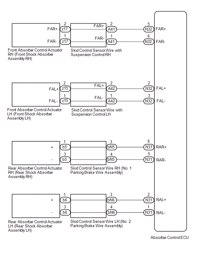
WIRING DIAGRAM
CAUTION / NOTICE / HINT
NOTICE:
- Before performing troubleshooting, inspect the connectors of related circuits.
-
Before replacing the absorber control ECU, perform all of the following:
-
Symptom simulation.
Click here
.gif)
-
DTC inspection.
Click here
-
Techstream inspection.
Click here
- If no malfunctions are found in other areas, replace the absorber control ECU.
-
Symptom simulation.
-
After replacing the absorber control ECU with a new one, perform registration of vehicle identification information.
Click here
PROCEDURE
| 1. | CLEAR DTCS |
(a) Clear the DTCs.
Click here
|

| 2. | PERFORM ACTIVE TEST USING TECHSTREAM (FOUR-WHEEL DAMPING FORCE FULL HARD/SOFT) |
(a) Turn the engine switch off.
(b) Connect the Techstream to the DLC3.
(c) Start the engine.
(d) Turn the Techstream on.
(e) Enter the following menus: Chassis / Air suspension /Active Test.
Chassis > Air suspension > Active Test| Tester Display | Measurement Item | Restrict Condition |
|---|---|---|
| Four-Wheel Damping Force Full Hard | Four-wheel damper step fixed at full hard |
|
| Four-Wheel Damping Force Full Soft | Four-wheel damper step fixed at full soft |
|
| Tester Display |
|---|
| Four-Wheel Damping Force Full Hard |
| Tester Display |
|---|
| Four-Wheel Damping Force Full Soft |
(f) When performing the Active Test, read each Tester Display item for the applicable wheel on the Data List and check the operation status of the absorber control actuator for the applicable wheel.
Chassis > Air suspension > Data List| Tester Display | Measurement Item | Range | Normal Condition | Diagnostic Note |
|---|---|---|---|---|
| FR Solenoid Aim Electric Current Level for Control | Target solenoid current value (front wheel RH) | Min.: 0 mA Max.: 2040 mA | Changes depending on target damping force | - |
| FL Solenoid Aim Electric Current Level for Control | Target solenoid current value (front wheel LH) | Min.: 0 mA Max.: 2040 mA | Changes depending on target damping force | - |
| RR Solenoid Aim Electric Current Level for Control | Target solenoid current value (rear wheel RH) | Min.: 0 mA Max.: 2040 mA | Changes depending on target damping force | - |
| RL Solenoid Aim Electric Current Level for Control | Target solenoid current value (rear wheel LH) | Min.: 0 mA Max.: 2040 mA | Changes depending on target damping force | - |
| FR Solenoid Drive Duty | Solenoid drive duty value (front wheel RH) | Min.: 0% Max.: 100% | Changes depending on target damping force | - |
| FL Solenoid Drive Duty | Solenoid drive duty value (front wheel LH) | Min.: 0% Max.: 100% | Changes depending on target damping force | - |
| RR Solenoid Drive Duty | Solenoid drive duty value (rear wheel RH) | Min.: 0% Max.: 100% | Changes depending on target damping force | - |
| RL Solenoid Drive Duty | Solenoid drive duty value (rear wheel LH) | Min.: 0% Max.: 100% | Changes depending on target damping force | - |
| FR Solenoid Electric Current | Solenoid current value (front wheel RH) | Min.: 0 mA Max.: 2040 mA | Changes depending on target damping force | - |
| FL Solenoid Electric Current | Solenoid current value (front wheel LH) | Min.: 0 mA Max.: 2040 mA | Changes depending on target damping force | - |
| RR Solenoid Electric Current | Solenoid current value (rear wheel RH) | Min.: 0 mA Max.: 2040 mA | Changes depending on target damping force | - |
| RL Solenoid Electric Current | Solenoid current value (rear wheel LH) | Min.: 0 mA Max.: 2040 mA | Changes depending on target damping force | - |
| Tester Display |
|---|
| FR Solenoid Aim Electric Current Level for Control |
| FL Solenoid Aim Electric Current Level for Control |
| RR Solenoid Aim Electric Current Level for Control |
| RL Solenoid Aim Electric Current Level for Control |
| FR Solenoid Drive Duty |
| FL Solenoid Drive Duty |
| RR Solenoid Drive Duty |
| RL Solenoid Drive Duty |
| FR Solenoid Electric Current |
| FL Solenoid Electric Current |
| RR Solenoid Electric Current |
| RL Solenoid Electric Current |
OK:
The Data List step numbers, drive duty values and current values change according to the operation of the Active Test.
| NG | .gif) | GO TO STEP 4 |
|
| 3. | RECONFIRM DTC |
(a) Check that the same DTC is output.
Click here
| Result | Proceed to |
|---|---|
| DTC is output | A |
| DTC is not output | B |
| B | | USE SIMULATION METHOD TO CHECK |
|
| 4. | INSPECT ABSORBER CONTROL ACTUATOR (SHOCK ABSORBER ASSEMBLY) |
(a) Turn the engine switch off.
(b) Inspect the absorber control actuator (shock absorber assembly).
for Front Side: Click here
for Rear Side: Click here
| Result | Proceed to |
|---|---|
| OK (for Front Side) | A |
| OK (for Rear Side) | B |
| NG (Front absorber control actuator RH (front shock absorber assembly RH) malfunction) | C |
| NG (Front absorber control actuator LH (front shock absorber assembly LH) malfunction) | D |
| NG (Rear absorber control actuator RH (rear shock absorber assembly RH) malfunction) | E |
| NG (Rear absorber control actuator LH (rear shock absorber assembly LH) malfunction) | F |
| B | | GO TO STEP 7 |
| C | | REPLACE FRONT ABSORBER CONTROL ACTUATOR RH (FRONT SHOCK ABSORBER ASSEMBLY RH) |
| D | | REPLACE FRONT ABSORBER CONTROL ACTUATOR LH (FRONT SHOCK ABSORBER ASSEMBLY LH) |
| E | | REPLACE REAR ABSORBER CONTROL ACTUATOR RH (REAR SHOCK ABSORBER ASSEMBLY RH) |
| F | | REPLACE REAR ABSORBER CONTROL ACTUATOR LH (REAR SHOCK ABSORBER ASSEMBLY LH) |
|
| 5. | INSPECT SKID CONTROL SENSOR WIRE WITH SUSPENSION CONTROL |
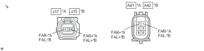
| *A | for RH | *B | for LH |
| *a | Component without harness connected (Skid Control Sensor Wire with Suspension Control) | - | - |
(a) Disconnect the z17 or z15 skid control sensor wire with suspension control connector.
(b) Disconnect the A41 or A42 skid control sensor wire with suspension control connector.
(c) Measure the resistance according to the value(s) in the table below.
Standard Resistance:
for RH| Tester Connection | Condition | Specified Condition |
|---|---|---|
| z17-2 (FAR+) - A41-2 (FAR+) | Always | Below 1 Ω |
| z17-1 (FAR-) - A41-1 (FAR-) | ||
| z17-2 (FAR+) or A41-2 (FAR+) - Body ground and other terminals | Always | 10 kΩ or higher |
| z17-1 (FAR-) or A41-1 (FAR-) - Body ground and other terminals |
| Tester Connection | Condition | Specified Condition |
|---|---|---|
| z15-2 (FAL+) - A42-2 (FAL+) | Always | Below 1 Ω |
| z15-1 (FAL-) - A42-1 (FAL-) | ||
| z15-2 (FAL+) or A42-2 (FAL+) - Body ground and other terminals | Always | 10 kΩ or higher |
| z15-1 (FAL-) or A42-1 (FAL-) - Body ground and other terminals |
| Result | Proceed to |
|---|---|
| OK | A |
| NG (for RH) | B |
| NG (for LH) | C |
| B | | REPLACE SKID CONTROL SENSOR WIRE WITH SUSPENSION CONTROL RH |
| C | | REPLACE SKID CONTROL SENSOR WIRE WITH SUSPENSION CONTROL LH |
|
| 6. | CHECK HARNESS AND CONNECTOR (SKID CONTROL SENSOR WIRE WITH SUSPENSION CONTROL - ABSORBER CONTROL ECU) |
(a) Disconnect the N32 absorber control ECU connector.
(b) Measure the resistance according to the value(s) in the table below.
Standard Resistance:
for Front RH| Tester Connection | Condition | Specified Condition |
|---|---|---|
| A41-2 (FAR+) - N32-5 (FAR+) | Always | Below 1 Ω |
| A41-1 (FAR-) - N32-6 (FAR-) | ||
| A41-2 (FAR+) or N32-5 (FAR+) - Body ground and other terminals | Always | 10 kΩ or higher |
| A41-1 (FAR-) or N32-6 (FAR-) - Body ground and other terminals |
| Tester Connection | Condition | Specified Condition |
|---|---|---|
| A42-2 (FAL+) - N32-2 (FAL+) | Always | Below 1 Ω |
| A42-1 (FAL-) - N32-3 (FAL-) | ||
| A42-2 (FAL+) or N32-2 (FAL+) - Body ground and other terminals | Always | 10 kΩ or higher |
| A42-1 (FAL-) or N32-3 (FAL-) - Body ground and other terminals |
| OK | | REPLACE ABSORBER CONTROL ECU |
| NG | | REPAIR OR REPLACE HARNESS OR CONNECTOR |
| 7. | INSPECT SKID CONTROL SENSOR WIRE (PARKING BRAKE WIRE ASSEMBLY) |
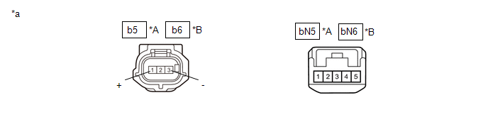
| *A | for RH | *B | for LH |
| *a | Component without harness connected (Skid Control Sensor Wire (Parking Brake Wire Assembly)) | - | - |
(a) Disconnect the b5 or b6 skid control sensor wire (parking brake wire assembly) connector.
(b) Disconnect the bN5 or bN6 skid control sensor wire (parking brake wire assembly) connector.
(c) Measure the resistance according to the value(s) in the table below.
Standard Resistance:
for RH| Tester Connection | Condition | Specified Condition |
|---|---|---|
| b5-1 (+) - bN5-3 | Always | Below 1 Ω |
| b5-3 (-) - bN5-4 | ||
| b5-1 (+) or bN5-3 - Body ground and other terminals | Always | 10 kΩ or higher |
| b5-3 (-) or bN5-4 - Body ground and other terminals |
| Tester Connection | Condition | Specified Condition |
|---|---|---|
| b6-1 (+) - bN6-3 | Always | Below 1 Ω |
| b6-3 (-) - bN6-4 | ||
| b6-1 (+) or bN6-3 - Body ground and other terminals | Always | 10 kΩ or higher |
| b6-3 (-) or bN6-4 - Body ground and other terminals |
| Result | Proceed to |
|---|---|
| OK | A |
| NG (for RH) | B |
| NG (for LH) | C |
| B | | REPLACE SKID CONTROL SENSOR WIRE RH (NO. 1 PARKING BRAKE WIRE ASSEMBLY) |
| C | | REPLACE SKID CONTROL SENSOR WIRE LH (NO. 2 PARKING BRAKE WIRE ASSEMBLY) |
|
| 8. | CHECK HARNESS AND CONNECTOR (SKID CONTROL SENSOR WIRE (PARKING BRAKE WIRE ASSEMBLY) - ABSORBER CONTROL ECU) |
(a) Disconnect the N31 absorber control ECU connector.
(b) Measure the resistance according to the value(s) in the table below.
Standard Resistance:
for Rear RH| Tester Connection | Condition | Specified Condition |
|---|---|---|
| bN5-3 - N31-6 (RAR+) | Always | Below 1 Ω |
| bN5-4 - N31-5 (RAR-) | ||
| bN5-3 or N31-6 (RAR+) - Body ground and other terminals | Always | 10 kΩ or higher |
| bN5-4 or N31-5 (RAR-) - Body ground and other terminals |
| Tester Connection | Condition | Specified Condition |
|---|---|---|
| bN6-3 - N31-2 (RAL+) | Always | Below 1 Ω |
| bN6-4 - N31-1 (RAL-) | ||
| bN6-3 or N31-2 (RAL+) - Body ground and other terminals | Always | 10 kΩ or higher |
| bN6-4 or N31-1 (RAL-) - Body ground and other terminals |
| OK | | REPLACE ABSORBER CONTROL ECU |
| NG | | REPAIR OR REPLACE HARNESS OR CONNECTOR |
READ NEXT:
 Suspension Control ECU Malfunction (C1781)
DESCRIPTION If a malfunction in the absorber control ECU is detected, DTC C1781 is stored. DTC No. Detection Item DTC Detection Condition Trouble Area Warning Indicate Memory C1781
Front Wheels Speed Sensor Signal Malfunction (C1783)
DESCRIPTION The speed sensors monitor the speed of the wheels and send an appropriate speed signal to the absorber control ECU through the skid control ECU (brake actuator assembly). If a malfunction
Steering Sensor Signal Malfunction (C1784)
DESCRIPTION Steering sensor signals are sent to the absorber control ECU via CAN communication. If a communication error is detected, DTC C1784 is stored. DTC No. Detection Item DTC Detection C
SEE MORE:
Front Passenger Side Power Mirror cannot be Adjusted with Power Mirror Switch
DESCRIPTION The outer mirror switch assembly sends the mirror adjust switch signals to the main body ECU (multiplex network body ECU). The main body ECU (multiplex network body ECU) then sends the received mirror adjust switch signals to the outer mirror control ECU assembly (front passenger door) v
Inspection
INSPECTION PROCEDURE 1. INSPECT WATER INLET WITH THERMOSTAT SUB-ASSEMBLY CAUTION:
Do not put your hands into the water that has been heated for the inspection.
Touching the heated water could result in burns.
HINT: The valve opening temperature is inscribed on the water inlet with therm
