Lexus ES: Flying Capacitor Circuit Voltage Out of Range (P1AFD00)
DESCRIPTION
The battery ECU assembly monitors its internal operation and will store these DTCs when it detects an internal malfunction.
| DTC No. | Detection Item | DTC Detection Condition | Trouble Area | MIL | Warning Indicate |
|---|---|---|---|---|---|
| P1AFD00 | Flying Capacitor Circuit Voltage Out of Range | ECU internal malfunction (1 trip detection logic) |
| Comes on | Master Warning Light: Comes on |
MONITOR DESCRIPTION
The battery ECU assembly monitors its internal operation. If the internal operation is malfunctioning, the battery ECU assembly illuminates the MIL and stores a DTC.
MONITOR STRATEGY
| Related DTCs | P1AFD (INF P1AFD00): Battery stack voltage sense circuit |
| Required sensors/components | Battery ECU assembly |
| Frequency of operation | Continuous |
| Duration | TMC's intellectual property |
| MIL operation | Immediately |
| Sequence of operation | None |
TYPICAL ENABLING CONDITIONS
| The monitor will run whenever the following DTCs are not stored | TMC's intellectual property |
| Other conditions belong to TMC's intellectual property | - |
TYPICAL MALFUNCTION THRESHOLDS
| TMC's intellectual property | - |
COMPONENT OPERATING RANGE
| Battery ECU assembly | DTC P1AFD (INF P1AFD00) is not detected |
CONFIRMATION DRIVING PATTERN
HINT:
-
After repair has been completed, clear the DTC and then check that the vehicle has returned to normal by performing the following All Readiness check procedure.
Click here
.gif)
-
When clearing the permanent DTCs, refer to the "CLEAR PERMANENT DTC" procedure.
Click here
- Connect the Techstream to the DLC3.
- Turn the power switch on (IG) and turn the Techstream on.
- Clear the DTCs (even if no DTCs are stored, perform the clear DTC procedure).
- Turn the power switch off and wait for 2 minutes or more.
- Turn the power switch on (IG) and turn the Techstream on.
-
With power switch on (IG) and wait for 30 seconds or more.[*1]
HINT:
[*1]: Normal judgment procedure.
The normal judgment procedure is used to complete DTC judgment and also used when clearing permanent DTCs.
- Enter the following menus: Powertrain / HV Battery / Utility / All Readiness.
-
Check the DTC judgment result.
HINT:
- If the judgment result shows NORMAL, the system is normal.
- If the judgment result shows ABNORMAL, the system has a malfunction.
- If the judgment result shows INCOMPLETE or N/A, perform the normal judgment procedure again.
CAUTION / NOTICE / HINT
CAUTION:
-
Before the following operations are conducted, take precautions to prevent electric shock by turning the power switch off, wearing insulated gloves, and removing the service plug grip from HV battery.
.png)
- Inspecting the high-voltage system
- Disconnecting the low voltage connector of the inverter with converter assembly
- Disconnecting the low voltage connector of the HV battery
-
To prevent electric shock, make sure to remove the service plug grip to cut off the high voltage circuit before servicing the vehicle.

-
After removing the service plug grip from the HV battery, put it in your pocket to prevent other technicians from accidentally reconnecting it while you are working on the high-voltage system.

-
After removing the service plug grip, wait for at least 10 minutes before touching any of the high-voltage connectors or terminals. After waiting for 10 minutes, check the voltage at the terminals in the inspection point in the inverter with converter assembly. The voltage should be 0 V before beginning work.

*a
Without waiting for 10 minutes
Click here
HINT:
Waiting for at least 10 minutes is required to discharge the high-voltage capacitor inside the inverter with converter assembly.
-
Make sure to insulate the high-voltage connectors and terminals of the HV battery with insulating tape after removing it.
If the HV battery stored without insulating the connectors and terminals, electric shock or fire may result.
-
When disposing of an HV battery, make sure to return it through an authorized collection agent who is capable of handling it safely. If the HV battery is returned via the manufacturer specified route, it will be returned properly and in a safe manner by an authorized collection agent.
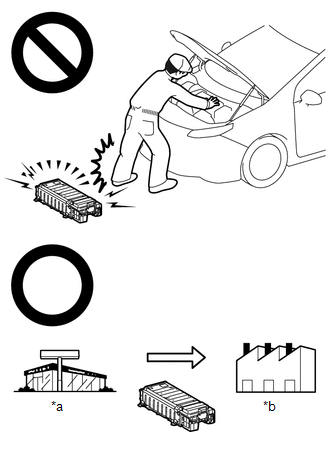
*a
Dealer
*b
Battery Collection Agent
- Accidents such as electric shock may result if the HV battery is disposed of improperly or abandoned. Therefore, make sure to return all HV batteries through an authorized collection agent.
-
Before returning the HV battery, make sure to perform a recovery inspection.
Click here
-
Before returning the HV supply stack sub-assembly, make sure to perform a recovery inspection.
Click here
- Make a note of the output DTCs as some of them may be necessary for recovery inspection of the HV battery and HV supply stack sub-assemblies.
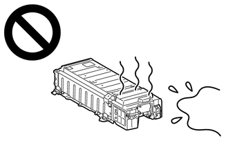
-
After removing the HV battery, keep it away from water. Exposure to water may cause the HV battery to produce heat, resulting in a fire.
NOTICE:
After turning the power switch off, waiting time may be required before disconnecting the cable from the negative (-) auxiliary battery terminal. Therefore, make sure to read the disconnecting the cable from the negative (-) auxiliary battery terminal notices before proceeding with work.
Click here
PROCEDURE
| 1. | CHECK DTC OUTPUT (HV BATTERY) |
(a) Connect the Techstream to the DLC3.
(b) Turn the power switch on (IG).
(c) Enter the following menus: Powertrain / HV Battery / Trouble Codes.
(d) Check for DTCs.
Powertrain > HV Battery > Trouble Codes| Result | Proceed to |
|---|---|
| "P1AFD00" only is output. | A |
| DTCs except "P1AFD00" are output. | B |
(e) Turn the power switch off.
| B | .gif) | GO TO DTC CHART (HYBRID BATTERY SYSTEM) |
|
.gif)
| 2. | CHECK CONNECTOR CONNECTION CONDITION (HV BATTERY HIGH VOLTAGE CONNECTOR) |
CAUTION:
Be sure to wear insulated gloves and protective goggles.
(a) Check that the service plug grip is not installed.
NOTICE:
After removing the service plug grip, do not turn the power switch on (READY), unless instructed by the repair manual because this may cause a malfunction.
(b) Remove the No. 1 HV battery hose.
Click here
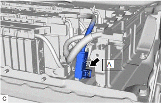
| (c) Check the connector connections and contact pressure of the relevant terminals for the HV supply stack sub-assembly connector. Click here OK: The connector is connected securely and there are no contact problems.
|
| ||||||||||||||||
(d) Install the No. 1 HV battery hose.
| A | | REPLACE BATTERY ECU ASSEMBLY |
| B | | CONNECT SECURELY |
| C | | REPLACE NO. 1 HV SUPPLY STACK SUB-ASSEMBLY |
| D | | REPLACE NO. 2 HV SUPPLY STACK SUB-ASSEMBLY |
READ NEXT:
 Flying Capacitor/Internal Control Module Hybrid/EV Battery Monitor Voltage Out of Range (P1AFD1C)
DESCRIPTION The battery ECU assembly monitors the HV battery voltage. If the battery ECU assembly detects a malfunction of its internal voltage detection circuits, it will store this DTC. HINT: If thi
Hybrid/EV Battery ECU Multiple Reset (P1AFF00)
DESCRIPTION The battery ECU assembly monitors its internal operation and will store these DTCs when it detects an internal malfunction. DTC No. Detection Item DTC Detection Condition Trouble
Hybrid/EV Battery Current Sensor for Driving Control Circuit Short to Ground (P1C9F11,P1C9F15)
DESCRIPTION Refer to the description for DTC P0ABF11. Click here DTC No. Detection Item DTC Detection Condition Trouble Area MIL Warning Indicate P1C9F11 Hybrid/EV Battery Current
SEE MORE:
Components
COMPONENTS ILLUSTRATION *1 REAR BUMPER ASSEMBLY *2 REAR COMBINATION LIGHT COVER LH *3 REAR COMBINATION LIGHT COVER RH - - ILLUSTRATION *A w/ Hands Free Power Trunk Lid - - *1 KICK DOOR CONTROL SENSOR WITH BRACKET - - ILLUSTRATION *A w/ Parking Supp
Motor Generator Control ECU Communication Stop Mode
DESCRIPTION Detection Item Symptom Trouble Area Motor Generator Control ECU Communication Stop Mode Any of the following conditions are met:
Communication stop for "Motor Generator" is indicated on the "Communication Bus Check" screen of the Techstream.
Click here
Communication
