Lexus ES: Hybrid/EV Battery Current Sensor for Driving Control Circuit Short to Ground (P1C9F11,P1C9F15)
DESCRIPTION
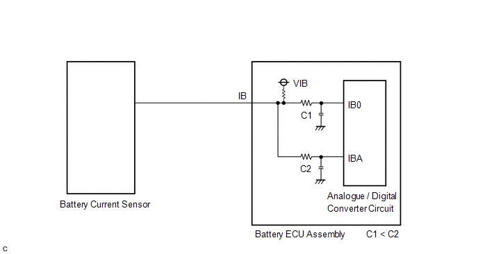
Refer to the description for DTC P0ABF11.
Click here .gif)
| DTC No. | Detection Item | DTC Detection Condition | Trouble Area | MIL | Warning Indicate |
|---|---|---|---|---|---|
| P1C9F11 | Hybrid/EV Battery Current Sensor for Driving Control Circuit Short to Ground | "Hybrid/EV Battery Current for Driving Control" is excessively low (terminal IBA voltage stuck at 5 V). (1 trip detection logic) | Battery ECU assembly | Comes on | Master Warning Light: Comes on |
| P1C9F15 | Hybrid/EV Battery Current Sensor for Driving Control Circuit Short to Auxiliary Battery or Open | "Hybrid/EV Battery Current for Driving Control" is excessively high (terminal IBA voltage stuck at 0 V). (1 trip detection logic) | Battery ECU assembly | Comes on | Master Warning Light: Comes on |
 Related Data List
 | DTC No. | Data List |
|---|---|
| P1C9F11 |
|
| P1C9F15 |
MONITOR DESCRIPTION
The battery ECU assembly monitors its internal circuit connected to the battery current sensor. If the battery ECU assembly detects a malfunction in this internal circuit, it will illuminate the MIL and store a DTC.
MONITOR STRATEGY
| Related DTCs | P1CA1 (INF P1C9F11): Hybrid/EV battery pack current sensor circuit malfunction (+B short) P1CA2 (INF P1C9F15): Hybrid/EV battery pack current sensor circuit malfunction (GND short) |
| Required sensors/components | Battery current sensor |
| Frequency of operation | Continuous |
| Duration | TMC's intellectual property |
| MIL operation | Immediately |
| Sequence of operation | None |
TYPICAL ENABLING CONDITIONS
| The monitor will run whenever the following DTCs are not stored | TMC's intellectual property |
| Other conditions belong to TMC's intellectual property | - |
TYPICAL MALFUNCTION THRESHOLDS
| TMC's intellectual property | - |
COMPONENT OPERATING RANGE
| Battery ECU assembly | DTC P1CA1 (INF P1C9F11) is not detected DTC P1CA2 (INF P1C9F15) is not detected |
CONFIRMATION DRIVING PATTERN
HINT:
-
After repair has been completed, clear the DTC and then check that the vehicle has returned to normal by performing the following All Readiness check procedure.
Click here
-
When clearing the permanent DTCs, refer to the "CLEAR PERMANENT DTC" procedure.
Click here
- Connect the Techstream to the DLC3.
- Turn the power switch on (IG) and turn the Techstream on.
- Clear the DTCs (even if no DTCs are stored, perform the clear DTC procedure).
- Turn the power switch off and wait for 2 minutes or more.
- Turn the power switch on (IG) and turn the Techstream on.
-
With power switch on (IG) and wait for 10 seconds or more.[*1]
HINT:
[*1]: Normal judgment procedure.
The normal judgment procedure is used to complete DTC judgment and also used when clearing permanent DTCs.
- Enter the following menus: Powertrain / HV Battery / Utility / All Readiness.
-
Check the DTC judgment result.
HINT:
- If the judgment result shows NORMAL, the system is normal.
- If the judgment result shows ABNORMAL, the system has a malfunction.
- If the judgment result shows INCOMPLETE or N/A, perform the normal judgment procedure again.
PROCEDURE
| 1. | CHECK DTC OUTPUT (HV BATTERY, HYBRID CONTROL) |
(a) Connect the Techstream to the DLC3.
(b) Turn the power switch on (IG).
(c) Enter the following menus: Powertrain / HV Battery and Hybrid Control / Trouble Codes.
(d) Check for DTCs.
Powertrain > HV Battery > Trouble Codes Powertrain > Hybrid Control > Trouble Codes| Result | Proceed to |
|---|---|
| "P1C9F11 or P1C9F15" only is output, or DTCs except the ones in the table below are also output. | A |
| DTCs of hybrid battery system in the table below are output. | B |
| DTCs of hybrid control system in the table below are output. | C |
| System | Relevant DTC | |
|---|---|---|
| Hybrid battery system | P060A47 | Hybrid/EV Battery Energy Control Module Monitoring Processor Watchdog / Safety MCU Failure |
| P060B49 | Hybrid/EV Battery Energy Control Module A/D Processing Internal Electronic Failure | |
| P060687 | Hybrid/EV Battery Energy Control Module Processor to Monitoring Processor Missing Message | |
| P0ABF11 | Hybrid/EV Battery Current Sensor "A" Circuit Short to Ground | |
| P0ABF15 | Hybrid/EV Battery Current Sensor "A" Circuit Short to Auxiliary Battery or Open | |
| P0ABF28 | Hybrid/EV Battery Current Sensor "A" Signal Bias Level Out of Range / Zero Adjustment Failure | |
| P0ABF2A | Hybrid/EV Battery Current Sensor "A" Signal Stuck In Range | |
| Hybrid control system | P0A1F94 | Hybrid/EV Battery Energy Control Module Unexpected Operation |
(e) Turn the power switch off.
| A | .gif) | REPLACE BATTERY ECU ASSEMBLY |
| B | | GO TO DTC CHART (HYBRID BATTERY SYSTEM) |
| C | | GO TO DTC CHART (HYBRID CONTROL SYSTEM) |
READ NEXT:
 High Voltage Power Resource Internal Electronic Failure (P1C8549)
DESCRIPTION The battery ECU assembly monitors an internal operation of the hybrid vehicle control ECU. If it detects a malfunction, it will be output this DTC and performs fail-safe control. DTC No
Hybrid/EV Battery Current Sensor for Driving Control Voltage Out of Range (P1C9F1C)
DESCRIPTION Refer to the description for DTC P0ABF11. Click here DTC No. Detection Item DTC Detection Condition Trouble Area MIL Warning Indicate P1C9F1C Hybrid/EV Battery Current
Hybrid/EV Battery Stack 1 Voltage Difference Out of Range (P1CC81E,P1CC91E)
DESCRIPTION The HV battery is composed of 70 cells (3.7 V each) in series. The battery ECU assembly monitors difference in voltage of each HV battery cell to detect malfunctions of the HV battery.
SEE MORE:
Fuel Rail Pressure Sensor "A" Circuit Short to Ground (P019011)
DESCRIPTION The fuel pressure sensor (for high pressure side) is installed on the fuel delivery pipe (for high pressure side). The fuel pressure sensor (for high pressure side) changes the fuel pressure for high pressure side into an electrical signal and sends the signal to the ECM. Then the ECM c
BSM Buzzer Malfunction (C2A5D)
DESCRIPTION This DTC is stored when the rear television camera assembly receives an RCTA buzzer circuit malfunction signal from the blind spot monitor sensor RH. DTC No. Detection Item DTC Detection Condition Trouble Area C2A5D BSM Buzzer Malfunction The RCTA buzzer circuit is abnor
