Lexus ES: Engine Oil Pressure Control Circuit Open (P06DA13)
DESCRIPTION
Refer to DTC P052477.
Click here .gif)
| DTC No. | Detection Item | DTC Detection Condition | Trouble Area | MIL | Memory | Note |
|---|---|---|---|---|---|---|
| P06DA13 | Engine Oil Pressure Control Circuit Open | Open or short in oil pressure control valve assembly circuit (1 trip detection logic). |
| Does not come on | DTC stored | SAE Code: P06DA |
MONITOR DESCRIPTION
This DTC is designed to detect an open or short in the oil pressure control valve assembly circuit. If the oil pressure control valve duty-cycle is excessively high or low while the power switch is on (IG) or the engine is running, the ECM will store this DTC.
CONFIRMATION DRIVING PATTERN
- Connect the Techstream to the DLC3.
- Turn the power switch on (IG).
- Turn the Techstream on.
- Clear the DTCs (even if no DTCs are stored, perform the clear DTC procedure).
- Turn the power switch off and wait for at least 30 seconds.
- Turn the power switch on (IG).
- Wait 10 seconds or more.
- Turn the Techstream on.
- Enter the following menus: Powertrain / Engine / Trouble Codes.
-
Read the pending DTCs.
HINT:
- If a pending DTC is output, the system is malfunctioning.
- If a pending DTC is not output, perform the following procedure.
- Enter the following menus: Powertrain / Engine / Utility / All Readiness.
- Input the DTC: P06DA13.
-
Check the DTC judgment result.
Techstream Display
Description
NORMAL
- DTC judgment completed
- System normal
ABNORMAL
- DTC judgment completed
- System abnormal
INCOMPLETE
- DTC judgment not completed
- Perform driving pattern after confirming DTC enabling conditions
HINT:
- If the judgment result is NORMAL, the system is normal.
- If the judgment result is ABNORMAL, the system has a malfunction.
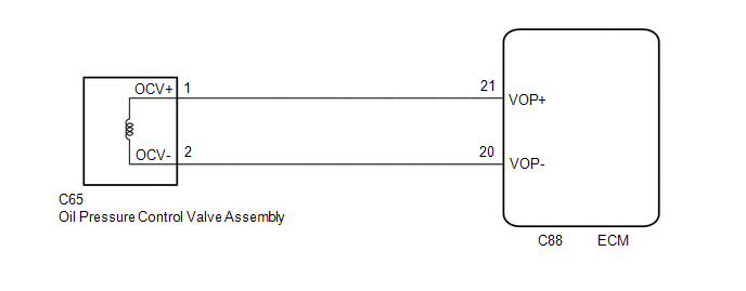
WIRING DIAGRAM
CAUTION / NOTICE / HINT
NOTICE:
-
Vehicle Control History may be stored in the hybrid vehicle control ECU assembly if the engine is malfunctioning. Certain vehicle condition information is recorded when Vehicle Control History is stored. Reading the vehicle conditions recorded in both the Freeze Frame Data and Vehicle Control History can be useful for troubleshooting.
Click here
(Select Powertrain in Health Check and then check the time stamp data.)
Click here
-
If any "Engine Malfunction" Vehicle Control History item has been stored in the hybrid vehicle control ECU assembly, make sure to clear it. However, as all Vehicle Control History items are cleared simultaneously, if any Vehicle Control History items other than "Engine Malfunction" are stored, make sure to perform any troubleshooting for them before clearing Vehicle Control History.
Click here
HINT:
Read Freeze Frame Data using the Techstream. The ECM records vehicle and driving condition information as Freeze Frame Data the moment a DTC is stored. When troubleshooting, Freeze Frame Data can help determine if the vehicle was moving or stationary, if the engine was warmed up or not, if the air fuel ratio was lean or rich, and other data from the time the malfunction occurred.
PROCEDURE
| 1. | INSPECT OIL PRESSURE CONTROL VALVE ASSEMBLY |
(a) Inspect the oil pressure control valve assembly.
Click here
| NG | .gif) | REPLACE OIL PRESSURE CONTROL VALVE ASSEMBLY |
|
.gif)
| 2. | CHECK HARNESS AND CONNECTOR (OIL PRESSURE CONTROL VALVE ASSEMBLY - ECM) |
(a) Disconnect the oil pressure control valve assembly connector.
(b) Disconnect the ECM connector.
(c) Measure the resistance according to the value(s) in the table below.
Standard Resistance:
| Tester Connection | Condition | Specified Condition |
|---|---|---|
| C65-1 (OCV+) - C88-21 (VOP+) | Always | Below 1 Ω |
| C65-2 (OCV-) - C88-20 (VOP-) | Always | Below 1 Ω |
| C65-1 (OCV+) or C88-21 (VOP+) - Body ground and other terminals | Always | 10 kΩ or higher |
| C65-2 (OCV-) or C88-20 (VOP-) - Body ground and other terminals | Always | 10 kΩ or higher |
| OK | | REPLACE ECM |
| NG | | REPAIR OR REPLACE HARNESS OR CONNECTOR |
READ NEXT:
 Evaporative Emission System Pressure / Intake Air Pressure Signal Compare Failure (P106A62,P106C62)
DESCRIPTION Those DTCs are designed to detect a deviation in the output characteristics of a pressure sensor. DTC No. Detection Item DTC Detection Condition Trouble Area MIL Memory Note
Fuel Rail Pressure Sensor (Low) Circuit Short to Ground (P107A11)
DESCRIPTION The No. 2 fuel pressure sensor (for low pressure side) replaces the fuel pressure with electrical signals and outputs them to the ECM. The ECM controls the optimal fuel pressure for the o
Fuel Rail Pressure Sensor (Low) Circuit Short to Battery or Open (P107A15)
DESCRIPTION Refer to DTC P107A11. Click here DTC No. Detection Item DTC Detection Condition Trouble Area MIL Memory Note P107A15 Fuel Rail Pressure Sensor (Low) Circuit Short to
SEE MORE:
Hybrid/EV Battery Stack 2 Cell Circuit Voltage Above Threshold (P1A6017,P31AA17)
DESCRIPTION The HV battery is composed of 70 cells (3.7 V each) in series. The battery ECU assembly monitors the voltage of each HV battery cell to detect malfunctions of the HV battery. DTC No. Detection Item DTC Detection Condition Trouble Area MIL Warning Indicate P1A6017 Hybri
Voice is not Recognized
PROCEDURE 1. CHECK CONDITION (a) While paying attention to the condition of the spoken voice command, perform a voice recognition operation. OK: Voice command is recognized normally. HINT:
When the voice command is recognized, the content of the voice command is displayed in the voice r
