Lexus ES: Fuel Rail Pressure Sensor (Low) Circuit Short to Battery or Open (P107A15)
DESCRIPTION
Refer to DTC P107A11.
Click here .gif)
| DTC No. | Detection Item | DTC Detection Condition | Trouble Area | MIL | Memory | Note |
|---|---|---|---|---|---|---|
| P107A15 | Fuel Rail Pressure Sensor (Low) Circuit Short to Battery or Open | The No. 2 fuel pressure sensor (for low pressure side) output voltage is higher than 4.85 V for 3 seconds or more (1 trip detection logic). |
| Comes on | DTC stored | SAE Code: P107D |
HINT:
When this DTC is output, check the fuel pressure (for low pressure side) in the Data List. Enter the following menus: Powertrain / Engine / Data List / Fuel Pressure (Low) / Fuel Pressure 2.
| DTC No. | Fuel Pressure (Low) / Fuel Pressure 2 | Malfunction |
|---|---|---|
| P107A15 | Approximately 750 kPa or higher |
|
If the Data List value is normal it may be due to a temporary recovery from the malfunction condition. Check for intermittent problems.
Click here
MONITOR DESCRIPTION
This DTC is stored if the No. 2 fuel pressure sensor (for low pressure side) output voltage is out of the standard range due to an open or short in the sensor circuit.
MONITOR STRATEGY
| Related DTCs | P107D: Fuel rail pressure sensor range check (High voltage) |
| Required Sensors/Components (Main) | No. 2 fuel pressure sensor (for low pressure side) |
| Required Sensors/Components (Related) | - |
| Frequency of Operation | Continuous |
| Duration | 3 seconds |
| MIL Operation | Immediate |
| Sequence of Operation | None |
TYPICAL ENABLING CONDITIONS
| Monitor runs whenever the following DTCs are not stored | None |
| Both of the following conditions are met | - |
| Auxiliary battery voltage | 8 V or higher |
| Power switch | On (IG) |
TYPICAL MALFUNCTION THRESHOLDS
| Fuel rail pressure sensor voltage | Higher than 4.85 V |
CONFIRMATION DRIVING PATTERN
HINT:
-
After repair has been completed, clear the DTC and then check that the vehicle has returned to normal by performing the following All Readiness check procedure.
Click here
-
When clearing the permanent DTCs, refer to the "CLEAR PERMANENT DTC" procedure.
Click here
- Connect the Techstream to the DLC3.
- Turn the power switch on (IG).
- Turn the Techstream on.
- Clear the DTCs (even if no DTCs are stored, perform the clear DTC procedure).
- Turn the power switch off and wait for at least 30 seconds.
- Turn the power switch on (IG).
- Turn the Techstream on.
-
Put the engine in Inspection Mode (Maintenance Mode).
Click here
- Start the engine.
- Idle the engine for 10 seconds or more [A].
- Enter the following menus: Powertrain / Engine / Trouble Codes [B].
-
Read the pending DTCs.
HINT:
- If a pending DTC is output, the system is malfunctioning.
- If a pending DTC is not output, perform the following procedure.
- Enter the following menus: Powertrain / Engine / Utility / All Readiness.
- Input the DTC: P107A15.
-
Check the DTC judgment result.
Techstream Display
Description
NORMAL
- DTC judgment completed
- System normal
ABNORMAL
- DTC judgment completed
- System abnormal
INCOMPLETE
- DTC judgment not completed
- Perform driving pattern after confirming DTC enabling conditions
HINT:
- If the judgment result is NORMAL, the system is normal.
- If the judgment result is ABNORMAL, the system has a malfunction.
- If the judgment result is INCOMPLETE, perform steps [A] through [B] again.
-
[A] to [B]: Normal judgment procedure.
The normal judgment procedure is used to complete DTC judgment and also used when clearing permanent DTCs.
- When clearing the permanent DTCs, do not disconnect the cable from the auxiliary battery terminal or attempt to clear the DTCs during this procedure, as doing so will clear the universal trip and normal judgment histories.
WIRING DIAGRAM
Refer to DTC P107A11.
Click here
CAUTION / NOTICE / HINT
NOTICE:
-
Vehicle Control History may be stored in the hybrid vehicle control ECU assembly if the engine is malfunctioning. Certain vehicle condition information is recorded when Vehicle Control History is stored. Reading the vehicle conditions recorded in both the Freeze Frame Data and Vehicle Control History can be useful for troubleshooting.
Click here
(Select Powertrain in Health Check and then check the time stamp data.)
Click here
-
If any "Engine Malfunction" Vehicle Control History item has been stored in the hybrid vehicle control ECU assembly, make sure to clear it. However, as all Vehicle Control History items are cleared simultaneously, if any Vehicle Control History items other than "Engine Malfunction" are stored, make sure to perform any troubleshooting for them before clearing Vehicle Control History.
Click here
HINT:
Read Freeze Frame Data using the Techstream. The ECM records vehicle and driving condition information as Freeze Frame Data the moment a DTC is stored. When troubleshooting, Freeze Frame Data can help determine if the vehicle was moving or stationary, if the engine was warmed up or not, if the air fuel ratio was lean or rich, and other data from the time the malfunction occurred.
PROCEDURE
| 1. | CHECK HARNESS AND CONNECTOR |
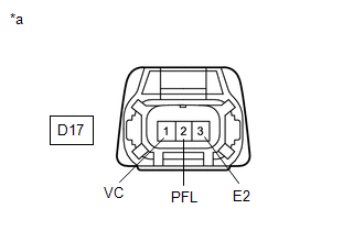
| *a | Front view of wire harness connector (to No. 2 Fuel Pressure Sensor (for Low Pressure Side)) |
HINT:
Make sure that the connector is properly connected. If it is not, securely connect it and check for DTCs again.
(a) Disconnect the No. 2 fuel pressure sensor (for low pressure side) connector.
(b) Turn the power switch on (IG).
(c) Measure the voltage according to the value(s) in the table below.
Standard Voltage:
| Tester Connection | Condition | Specified Condition |
|---|---|---|
| D17-1 (VC) - D17-3 (E2) | Power switch on (IG) | 4.75 to 5.25 V |
| D17-2 (PFL) - D17-3 (E2) | Power switch on (IG) | 4.4 to 5.6 V |
(d) Turn the power switch off and wait for at least 30 seconds.
(e) Measure the resistance according to the value(s) in the table below.
Standard Resistance:
| Tester Connection | Condition | Specified Condition |
|---|---|---|
| D17-3 (E2) - Body ground | Power switch off | Below 1 Ω |
| D17-1 (VC) - D17-2 (PFL) | Power switch off | 171 to 189 kΩ |
HINT:
Perform "Inspection After Repair" after replacing the No. 2 fuel pressure sensor (for low pressure side).
Click here
| OK | .gif) | REPLACE NO. 2 FUEL PRESSURE SENSOR (FOR LOW PRESSURE SIDE) |
|

| 2. | CHECK HARNESS AND CONNECTOR (NO. 2 FUEL PRESSURE SENSOR (FOR LOW PRESSURE SIDE) - ECM) |
(a) Disconnect the No. 2 fuel pressure sensor (for low pressure side) connector.
(b) Disconnect the ECM connector.
(c) Measure the resistance according to the value(s) in the table below.
Standard Resistance:
| Tester Connection | Condition | Specified Condition |
|---|---|---|
| D17-3 (E2) - C88-61 (EPFL) | Always | Below 1 Ω |
| D17-2 (PFL) - C88-107 (PFL) | Always | Below 1 Ω |
| D17-2 (PFL) or C88-107 (PFL) - Other terminals | Always | 10 kΩ or higher |
| OK | | REPLACE ECM |
| NG | | REPAIR OR REPLACE HARNESS OR CONNECTOR |
READ NEXT:
 Fuel Rail Pressure Sensor (Low) Signal Stuck in Range (P107A2A,P107A64)
DESCRIPTION Refer to DTC P107A11. Click here DTC No. Detection Item DTC Detection Condition Trouble Area MIL Memory Note P107A2A Fuel Rail Pressure Sensor (Low) Signal Stuck in
Control Module Internal Temperature Sensor/Intake Air Temperature Sensor Signal Compare Failure (P111C62)
DESCRIPTION The engine has an ECM internal temperature sensor and intake air temperature sensor. The resistance of a thermistor within the ECM internal temperature sensor and intake air temperature se
Bank 1 Air-Fuel Ratio Imbalance (Port) (P11EA00,P11EC00-P11EF00,P219A00,P219C00-P219F00)
DESCRIPTION Refer to DTC P003012. Click here Refer to DTC P030000. Click here DTC No. Detection Item DTC Detection Condition Trouble Area MIL Memory Note P11EA00 Bank 1 Air-Fu
SEE MORE:
Components
COMPONENTS ILLUSTRATION *1 LUGGAGE COMPARTMENT FLOOR MAT *2 SPARE WHEEL COVER TRAY ILLUSTRATION *1 REAR FLOOR FINISH PLATE *2 LUGGAGE HOLD BELT STRIKER ASSEMBLY ILLUSTRATION *A for LH Side *B for RH Side *C w/o Power Trunk Lid System *D w/ Power Trunk Li
System Description
SYSTEM DESCRIPTION FUNCTION OF MAIN COMPONENTS Component Function Multiplex tilt and telescopic ECU This ECU sends a control signal to the tilt motor (steering column assembly) and telescopic motor (steering column assembly), based on signals from each switch, to adjust the steering posit
