Lexus ES: Ignition Circuit
DESCRIPTION
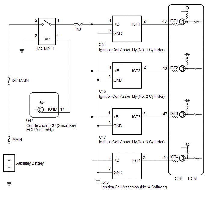
A direct ignition system is used on this vehicle. The direct ignition system is a 1 cylinder ignition system which ignites one cylinder with one ignition coil. In the 1 cylinder ignition system, one spark plug is connected to the end of the secondary winding. High voltage is generated in the secondary winding and is applied directly to the spark plug. The spark of the spark plug passes from the center electrode to the ground electrode.
The ECM determines the ignition timing and transmits the ignition signals for each cylinder. Using the ignition signal, the ECM turns on and off the power transistor inside the igniter, which switches on and off a current to the primary coil. When the current to the primary coil is cut off, high voltage is generated in the secondary coil and this voltage is applied to the spark plugs to create sparks inside the cylinders.
WIRING DIAGRAM
CAUTION / NOTICE / HINT
NOTICE:
Inspect the fuses for circuits related to this system before performing the following procedure.
HINT:
Perform a spark test before proceeding. If there is no spark for any cylinder, inspect this circuit.
Click here .gif)
PROCEDURE
| 1. | CHECK TERMINAL VOLTAGE (POWER SOURCE OF IGNITION COIL ASSEMBLY) |
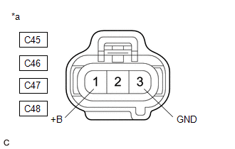
| *a | Front view of wire harness connector (to Ignition Coil Assembly) |
(a) Disconnect the ignition coil assembly connectors.
(b) Turn the power switch on (IG).
(c) Measure the voltage according to the value(s) in the table below.
Standard Voltage:
| Tester Connection | Condition | Specified Condition |
|---|---|---|
| C45-1 (+B) - C45-3 (GND) | Power switch on (IG) | 11 to 14 V |
| C46-1 (+B) - C46-3 (GND) | Power switch on (IG) | 11 to 14 V |
| C47-1 (+B) - C47-3 (GND) | Power switch on (IG) | 11 to 14 V |
| C48-1 (+B) - C48-3 (GND) | Power switch on (IG) | 11 to 14 V |
| NG | .gif) | GO TO STEP 3 |
|
.gif)
| 2. | CHECK HARNESS AND CONNECTOR (IGNITION COIL ASSEMBLY - ECM) |
(a) Disconnect the ignition coil assembly connectors.
(b) Disconnect the ECM connector.
(c) Measure the resistance according to the value(s) in the table below.
Standard Resistance:
| Tester Connection | Condition | Specified Condition |
|---|---|---|
| C45-2 (IGT1) - C88-49 (IGT1) | Always | Below 1 Ω |
| C46-2 (IGT2) - C88-48 (IGT2) | Always | Below 1 Ω |
| C47-2 (IGT3) - C88-47 (IGT3) | Always | Below 1 Ω |
| C48-2 (IGT4) - C88-46 (IGT4) | Always | Below 1 Ω |
| C45-2 (IGT1) or C88-49 (IGT1) - Body ground and other terminals | Always | 10 kΩ or higher |
| C46-2 (IGT2) or C88-48 (IGT2) - Body ground and other terminals | Always | 10 kΩ or higher |
| C47-2 (IGT3) or C88-47 (IGT3) - Body ground and other terminals | Always | 10 kΩ or higher |
| C48-2 (IGT4) or C88-46 (IGT4) - Body ground and other terminals | Always | 10 kΩ or higher |
| OK | | REPLACE ECM |
| NG | | REPAIR OR REPLACE HARNESS OR CONNECTOR |
| 3. | CHECK HARNESS AND CONNECTOR (IGNITION COIL ASSEMBLY - BODY GROUND) |
(a) Disconnect the ignition coil assembly connectors.
(b) Measure the resistance according to the value(s) in the table below.
Standard Resistance:
| Tester Connection | Condition | Specified Condition |
|---|---|---|
| C45-3 (GND) - Body ground | Always | Below 1 Ω |
| C46-3 (GND) - Body ground | Always | Below 1 Ω |
| C47-3 (GND) - Body ground | Always | Below 1 Ω |
| C48-3 (GND) - Body ground | Always | Below 1 Ω |
| NG | | REPAIR OR REPLACE HARNESS OR CONNECTOR |
|
| 4. | CHECK HARNESS AND CONNECTOR (IG2 NO. 1 RELAY - IGNITION COIL ASSEMBLY) |
(a) Disconnect the IG2 NO. 1 relay from No. 1 engine room relay block and No. 1 junction block assembly.
(b) Disconnect the ignition coil assembly connectors.
(c) Measure the resistance according to the value(s) in the table below.
Standard Resistance:
| Tester Connection | Condition | Specified Condition |
|---|---|---|
| 3 (IG2 NO. 1 relay) - C45-1 (+B) | Always | Below 1 Ω |
| 3 (IG2 NO. 1 relay) - C46-1 (+B) | Always | Below 1 Ω |
| 3 (IG2 NO. 1 relay) - C47-1 (+B) | Always | Below 1 Ω |
| 3 (IG2 NO. 1 relay) - C48-1 (+B) | Always | Below 1 Ω |
| 3 (IG2 NO. 1 relay) or C45-1 (+B) - Body ground and other terminals | Always | 10 kΩ or higher |
| 3 (IG2 NO. 1 relay) or C46-1 (+B) - Body ground and other terminals | Always | 10 kΩ or higher |
| 3 (IG2 NO. 1 relay) or C47-1 (+B) - Body ground and other terminals | Always | 10 kΩ or higher |
| 3 (IG2 NO. 1 relay) or C48-1 (+B) - Body ground and other terminals | Always | 10 kΩ or higher |
| OK | | GO TO ECM POWER SOURCE CIRCUIT |
| NG | | REPAIR OR REPLACE HARNESS OR CONNECTOR |
READ NEXT:
 Rough Idling
DESCRIPTION Problem Symptom Suspected Area Trouble Area
Engine speed fluctuation due to abnormal combustion
Idle speed too low or high
Strong engine vibration due to above symptoms
Rough Idling
DESCRIPTION Problem Symptom Suspected Area Trouble Area
Engine speed fluctuation due to abnormal combustion
Idle speed too low or high
Strong engine vibration due to above symptoms
SEE MORE:
Control Module Performance Bank 2 Component Internal Failure (P060596,P060796)
MONITOR DESCRIPTION The ECM continuously monitors its internal processors (CPUs) and heated oxygen sensor transistors. This self-check ensures that the ECM is functioning properly. DTC No. Detection Item DTC Detection Condition Trouble Area MIL Memory Note P060596 Control Module
Automatic High Beam Switch Indicator does not Come ON
DESCRIPTION When the automatic high beam system is on, the steering sensor illuminates the automatic high beam switch indicator. WIRING DIAGRAM PROCEDURE 1. READ VALUE USING TECHSTREAM (a) Connect the Techstream to the DLC3. (b) Turn the engine switch on (IG). (c) Turn the Techstream on. (
