Lexus ES: GVIF Disconnected (from EMV/MM Integrated Device to Multi Display) (B1575)
DESCRIPTION
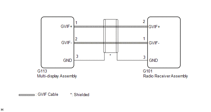
The radio receiver assembly and multi-display assembly are connected via video signal (digital) lines.
This DTC is stored when a video signal (digital) line is disconnected.
| DTC No. | Detection Item | DTC Detection Condition | Trouble Area |
|---|---|---|---|
| B1575 | GVIF Disconnected (from EMV/MM Integrated Device to Multi Display) | GVIF disconnected (from radio receiver assembly to multi-display assembly) |
|
WIRING DIAGRAM
CAUTION / NOTICE / HINT
NOTICE:
-
Depending on the parts that are replaced during vehicle inspection or maintenance, performing initialization, registration or calibration may be needed. Refer to Precaution for Navigation System.
Click here
.gif)
-
When replacing the radio receiver assembly, always replace it with a new one. If a radio receiver assembly which was installed to another vehicle is used, the following may occur:
- A communication malfunction DTC may be stored.
- The radio receiver assembly may not operate normally.
PROCEDURE
| 1. | CHECK DTC |
(a) Clear the DTCs.
Body Electrical > Navigation System > Clear DTCs(b) Turn the engine switch off.
(c) Recheck for DTCs and check that no DTCs are output.
Body Electrical > Navigation System > Trouble CodesOK:
No DTCs are output.
| OK |  | USE SIMULATION METHOD TO CHECK |
|

| 2. | CHECK HARNESS AND CONNECTOR (MULTI-DISPLAY ASSEMBLY - RADIO RECEIVER ASSEMBLY) |
| (a) Disconnect the G113 multi-display assembly connector. |
|
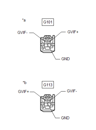
(b) Disconnect the G101 radio receiver assembly connector.
(c) Measure the resistance according to the value(s) in the table below.
Standard Resistance:
| Tester Connection | Condition | Specified Condition |
|---|---|---|
| G101-2 (GVIF+) - G113-1 (GVIF+) | Always | Below 1 Ω |
| G101-1 (GVIF-) - G113-2 (GVIF-) | Always | Below 1 Ω |
| G101-3 (GND) - G113-3 (GND) | Always | Below 1 Ω |
| G101-2 (GVIF+) or G113-1 (GVIF+) - Body ground | Always | 10 kΩ or higher |
| G101-1 (GVIF-) or G113-2 (GVIF-) - Body ground | Always | 10 kΩ or higher |
| G101-3 (GND) or G113-3 (GND) - Body ground | Always | 10 kΩ or higher |
| NG | | REPAIR OR REPLACE HARNESS OR CONNECTOR |
|
| 3. | CHECK MULTI-DISPLAY ASSEMBLY |
(a) Replace the multi-display assembly with a new or known good one.
Click here
(b) Clear the DTCs.
Body Electrical > Navigation System > Clear DTCs(c) Turn the engine switch off.
(d) Recheck for DTCs and check that no DTCs are output.
Body Electrical > Navigation System > Trouble CodesOK:
No DTCs are output.
| OK | | END (MULTI-DISPLAY ASSEMBLY IS DEFECTIVE) |
| NG | | REPLACE RADIO RECEIVER ASSEMBLY |
READ NEXT:
 Voice Recognition Microphone Disconnected (B1579)
DESCRIPTION The radio receiver assembly and telephone microphone assembly are connected to each other using the microphone connection detection signal lines. This DTC is stored when a microphone conne
USB Device Malfunction (B1585)
DESCRIPTION This DTC is stored when a malfunction occurs in a connected device. DTC No. Detection Item DTC Detection Condition Trouble Area B1585 USB Device Malfunction When any of th
Black Screen
PROCEDURE 1. CHECK DISPLAY SETTING (a) Check that the display is not in screen off mode. OK: The display setting is not in screen off mode. NG CHANGE SCREEN TO SCREEN ON MODE
SEE MORE:
Transfer Case Front Oil Seal (for Lh Side)
ComponentsCOMPONENTS ILLUSTRATION *1 TRANSFER AND TRANSAXLE SETTING STUD BOLT *2 TRANSFER CASE OIL SEAL N*m (kgf*cm, ft.*lbf): Specified torque ● Non-reusable part MP grease ★ Precoated part
Front Left Sensor Malfunction (C1AE1)
DESCRIPTION The front corner ultrasonic sensor LH is installed to the front bumper. The clearance warning ECU assembly detects obstacles based on signals received from the front corner ultrasonic sensor LH. If the front corner ultrasonic sensor LH has an open circuit or other malfunction, it will no
