Lexus ES: Disassembly
DISASSEMBLY
PROCEDURE
1. REMOVE KICK DOOR CONTROL SENSOR WITH BRACKET (w/ Hands Free Power Trunk Lid)
Click here .gif)
2. REMOVE REAR CENTER ULTRASONIC SENSOR (w/ Parking Support Alert System)
Click here
HINT:
Use the same procedure for the RH side and LH side.
3. REMOVE REAR CORNER ULTRASONIC SENSOR (w/ Parking Support Alert System)
Click here
HINT:
Use the same procedure for the RH side and LH side.
4. REMOVE REAR CENTER ULTRASONIC SENSOR RETAINER (w/ Parking Support Alert System)
Click here
HINT:
Use the same procedure for the RH side and LH side.
5. REMOVE REAR CORNER ULTRASONIC SENSOR RETAINER (w/ Parking Support Alert System)
Click here
HINT:
Use the same procedure for the RH side and LH side.
6. REMOVE NO. 2 LUGGAGE ROOM WIRE (w/ Wire Harness)
Click here
7. REMOVE ULTRASONIC SENSOR CLIP (w/ Wire Harness)
Click here
8. REMOVE NO. 1 MOULDING TAPE
Click here
9. REMOVE REAR BUMPER PAD LH
Click here
10. REMOVE REAR BUMPER PAD RH
Click here
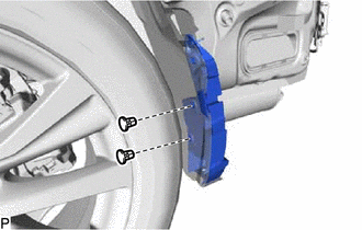
11. REMOVE REFLEX REFLECTOR ASSEMBLY LH
| (a) Remove the screw. |
|
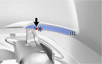
(b) Disengage the claw and guide to remove the reflex reflector assembly.
12. REMOVE REFLEX REFLECTOR ASSEMBLY RH
HINT:
Use the same procedure as for the LH side.
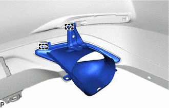
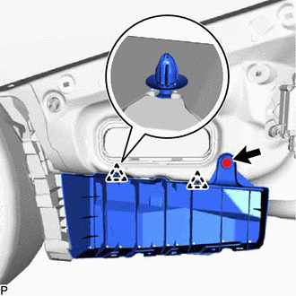
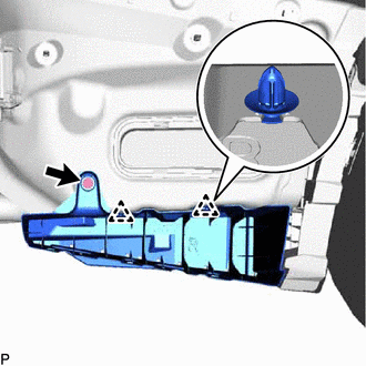
13. REMOVE REAR BUMPER EXTENSION SUB-ASSEMBLY LH
| (a) Remove the 4 screws. |
|
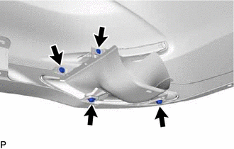
| (b) Remove the 4 grommets. |
|
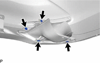
| (c) Disengage the 2 guides to remove the rear bumper extension sub-assembly. |
|
14. REMOVE REAR BUMPER EXTENSION SUB-ASSEMBLY RH
HINT:
Use the same procedure as for the LH side.
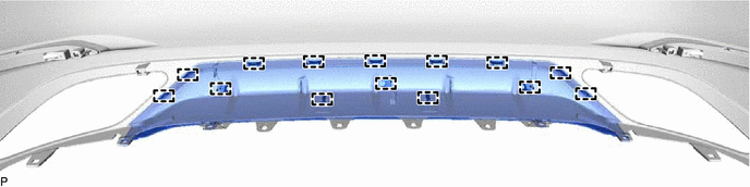
15. REMOVE CENTER REAR BUMPER EXTENSION SUB-ASSEMBLY (for Mesh Type Radiator Grille)
(a) Remove the 9 outside moulding retainers and 2 clips.
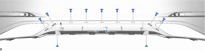
(b) Disengage the 14 guides to remove the center rear bumper extension sub-assembly.
16. REMOVE NO. 2 REAR BUMPER SIDE SUPPORT LH
Click here
17. REMOVE NO. 2 REAR BUMPER SIDE SUPPORT RH
HINT:
Use the same procedure as for the LH side.
18. REMOVE LUGGAGE COMPARTMENT FLOOR MAT
Click here
19. REMOVE SPARE WHEEL COVER TRAY
Click here
20. REMOVE REAR FLOOR FINISH PLATE
Click here
21. REMOVE LUGGAGE COMPARTMENT TRIM COVER RH
Click here
22. REMOVE LUGGAGE COMPARTMENT TRIM COVER LH
Click here
23. REMOVE LUGGAGE COMPARTMENT TRIM INNER COVER RH
Click here
24. REMOVE LUGGAGE COMPARTMENT TRIM INNER COVER LH
Click here
25. REMOVE REAR COMBINATION LIGHT LENS AND BODY LH
Click here
26. REMOVE REAR COMBINATION LIGHT LENS AND BODY RH
HINT:
Use the same procedure as for the LH side.
27. REMOVE REAR BUMPER UPPER RETAINER LH
Click here
28. REMOVE REAR BUMPER UPPER RETAINER RH
HINT:
Use the same procedure as for the LH side.
29. REMOVE NO. 2 REAR BUMPER SIDE RETAINER LH (for TMC Made)
| (a) Disengage the 3 claws to remove the No. 2 rear bumper side retainer LH. |
|
30. REMOVE NO. 2 REAR BUMPER SIDE RETAINER RH (for TMC Made)
| (a) Disengage the 3 claws to remove the No. 2 rear bumper side retainer RH. |
|
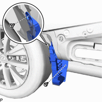
31. REMOVE LOWER REAR BUMPER SIDE RETAINER LH
| (a) Remove the screw. |
|
(b) Disengage the 2 clips to remove the lower rear bumper side retainer LH.
32. REMOVE LOWER REAR BUMPER SIDE RETAINER RH
| (a) Remove the screw. |
|
(b) Disengage the 2 clips to remove the lower rear bumper side retainer RH.
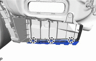
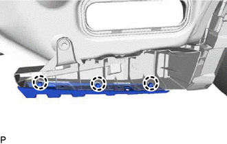
33. REMOVE REAR BUMPER SIDE SUPPORT LH
| (a) Remove the 2 grommets. |
|
| (b) Remove the 2 clips and rear bumper side support LH. |
|
34. REMOVE REAR BUMPER SIDE SUPPORT RH
HINT:
Use the same procedure as for the LH side.
35. REMOVE REAR BUMPER ENERGY ABSORBER
Click here
36. REMOVE REAR BUMPER PROTECTOR LH
Click here
37. REMOVE REAR BUMPER PROTECTOR RH
HINT:
Use the same procedure as for the LH side.
38. REMOVE REAR BUMPER PROTECTOR INSERT LH
Click here
39. REMOVE REAR BUMPER PROTECTOR INSERT RH
HINT:
Use the same procedure as for the LH side.
40. REMOVE REAR BUMPER REINFORCEMENT
Click here
READ NEXT:
 Reassembly
REASSEMBLY PROCEDURE 1. INSTALL REAR BUMPER REINFORCEMENT Click here 2. INSTALL REAR BUMPER PROTECTOR INSERT LH Click here 3. INSTALL REAR BUMPER PROTECTOR INSERT RH HINT: Use the same procedure a
Installation
INSTALLATION PROCEDURE 1. INSTALL REAR BUMPER ASSEMBLY (a) w/ Wire Harness: (1) Connect the connector. (b) Engage the 6 claws as shown in the illustration. Install in this Direction (c) Enga
SEE MORE:
Hybrid/EV Battery Negative Contactor Circuit Short to Ground (P0ADD11)
DESCRIPTION Refer to the description for DTC P0AE411. Click here DTC No. Detection Item DTC Detection Condition Trouble Area MIL Warning Indicate P0ADD11 Hybrid/EV Battery Negative Contactor Circuit Short to Ground Short to ground in the SMRG circuit: Primary circuit of SMR (-
Diagnostic Trouble Code Chart
DIAGNOSTIC TROUBLE CODE CHART Wiper and Washer System DTC No. Detection Item DTC Output from Link B1245 Lost Communication with Wiper ECU LIN Main Body B1279 Lost Communication with Humidity/Rain Sensor LIN Main Body B1370 ECU Malfunction Windshield wiper m
