Lexus ES: Absorber Control Switch
Components
COMPONENTS
ILLUSTRATION
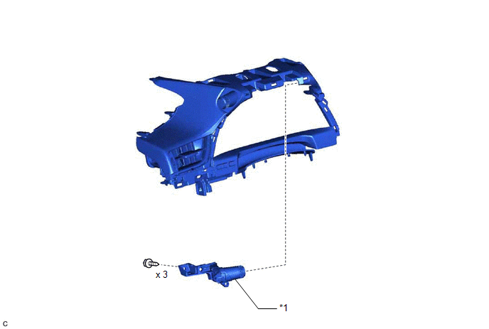
| *1 | DRIVE MODE SELECT SWITCH (COMBINATION SWITCH ASSEMBLY) | - | - |
Removal
REMOVAL
PROCEDURE
1. REMOVE DRIVE MODE SELECT SWITCH (COMBINATION SWITCH ASSEMBLY)
Click here .gif)
Inspection
INSPECTION
PROCEDURE
1. INSPECT DRIVE MODE SELECT SWITCH (COMBINATION SWITCH ASSEMBLY)
| (a) Measure the resistance according to the value(s) in the table below. Standard Resistance:
If the result is not as specified, replace the drive mode select switch (combination switch assembly). |
|
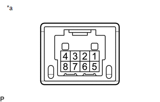
(b) Inspect the illumination:
(1) Apply battery voltage to the drive mode select switch (combination switch assembly) and check that the switch illuminates.
OK:
| Condition | Specified Condition |
|---|---|
| Battery positive (+) → Terminal 1 Battery negative (-) → Terminal 8 | Illuminates |
If the result is not as specified, replace the drive mode select switch (combination switch assembly).
READ NEXT:
 Precaution
PRECAUTION PRECAUTION FOR DISCONNECTING CABLE FROM NEGATIVE AUXILIARY BATTERY TERMINAL NOTICE: When disconnecting the cable from the negative (-) auxiliary battery terminal, initialize the following s
Parts Location
PARTS LOCATION ILLUSTRATION *1 FRONT ABSORBER CONTROL ACTUATOR RH (FRONT SHOCK ABSORBER ASSEMBLY RH) *2 FRONT ABSORBER CONTROL ACTUATOR LH (FRONT SHOCK ABSORBER ASSEMBLY LH) *3 REAR AB
SEE MORE:
Components
COMPONENTS ILLUSTRATION *1 SHIFT LEVER KNOB SUB-ASSEMBLY *2 SHIFT LOCK RELEASE BUTTON COVER *3 TRANSMISSION CONTROL CABLE ASSEMBLY *4 TRANSMISSION FLOOR SHIFT ASSEMBLY *5 REAR UPPER CONSOLE PANEL SUB-ASSEMBLY *6 NO. 1 CONSOLE BOX DUCT *7 UPPER CONSOLE PANEL SUB-AS
Software Incompatibility with Cruise Control Module Invalid/Incompatible Software Component (U030557)
DESCRIPTION The millimeter wave radar sensor assembly receives vehicle information from the forward recognition camera via CAN communication. If the vehicle information stored in the forward recognition camera differs from that stored in the millimeter wave radar sensor assembly, the millimeter wave
