Lexus ES: Disassembly
DISASSEMBLY
PROCEDURE
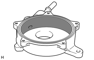
1. REMOVE END COVER
| (a) To prevent the coupling of the vacuum pump assembly from contacting the workbench, support the vacuum pump assembly with wooden blocks or an equivalent object. |
|
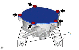
(b) Using a T30 "TORX" socket wrench, remove the 5 screws and end cover.
NOTICE:
- Hold the pump so that the pump installation surface and fitting parts will not be damaged.
- As the housing deforms when force is applied, do not secure the housing with a tool such as a vise.
- Securely fit the T30 "TORX" socket wrench to the screws.
- Do not drop the end cover.
- Do not damage the end cover.
- As there will be a small amount of oil remaining in the vacuum pump housing, be careful not to spill the oil when removing the end cover.
-
Do not rotate the coupling as oil remaining in the vacuum pump housing may be discharged.
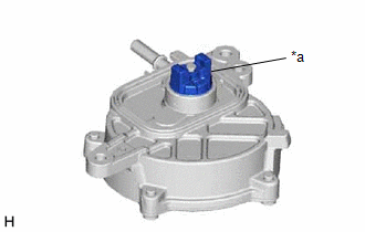
*a
Do not rotate the coupling.
- As the vacuum pump vane cap may become damaged, do not rotate the coupling counterclockwise.
| (c) Using a screwdriver with its tip wrapped with protective tape, remove the vacuum pump cover O-ring. NOTICE: Do not damage the groove. |
|
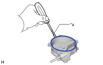
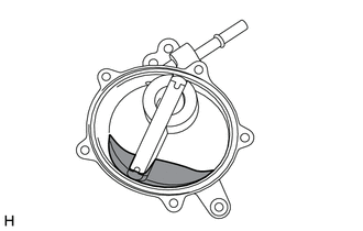
(d) Check that there is no foreign matter in the engine oil remaining in the vacuum pump housing.
If there is foreign matter, replace the vacuum pump assembly.
.png) | Engine Oil |
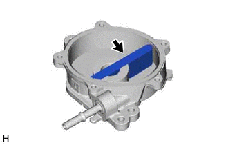
2. REMOVE VACUUM PUMP VANE AND VACUUM PUMP VANE CAP
| (a) Remove the vacuum pump vane together with the 2 vacuum pump vane caps. |
|
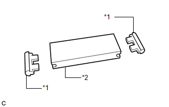
| (b) Remove the 2 vacuum pump vane caps from the vacuum pump vane. |
|
(c) Check that there is no damage such as cracks or fractures in the vacuum pump vane and vacuum pump vane cap.
If there is damage, replace the vacuum pump assembly.
3. REMOVE VACUUM PUMP ROTOR
(a) Remove the vacuum pump rotor from the vacuum pump housing.
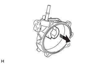
.png) | Remove in this Direction |
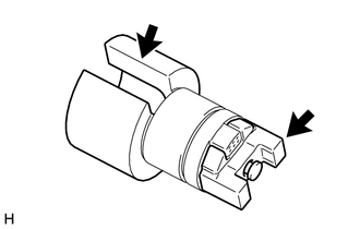
| (b) Check that there is no damage such as cracks or fractures in the vacuum pump rotor in the areas shown in the illustration. If there is damage, replace the vacuum pump assembly. |
|
4. INSPECT VACUUM PUMP HOUSING
(a) Check that there is no foreign matter in the vacuum pump housing.
If there is foreign matter, replace the vacuum pump assembly.
| | Contact Surface of Vacuum Pump Vane Cap |
(b) Visually inspect the contact surface of the vacuum pump vane cap of the vacuum pump housing.
If there is damage, replace the vacuum pump assembly.
READ NEXT:
 Installation
INSTALLATION CAUTION / NOTICE / HINT NOTICE: This procedure includes the installation of small-head bolts. Refer to Small-Head Bolts of Basic Repair Hint to identify the small-head bolts. Click here
On-vehicle Inspection
ON-VEHICLE INSPECTION PROCEDURE 1. OPERATION CHECK (a) Disconnect the No. 1 vacuum hose connector from the vacuum pump assembly. Click here (b) Connect the hose of the vacuum gauge to the vacuum
Reassembly
REASSEMBLY PROCEDURE 1. CLEAN VACUUM PUMP HOUSING (a) Clean the inside surface of the vacuum pump housing. 2. INSTALL VACUUM PUMP ROTOR (a) Clean the vacuum pump rotor. (b) Apply engine oil to the are
SEE MORE:
Lost Communication with ECM/PCM "A" Missing Message (U010087,...,U117587)
DESCRIPTION The hybrid vehicle control ECU transmits and receives signals via CAN communication to and from the ECM, yaw rate sensor, skid control ECU assembly, power steering ECU assembly, main body ECU, airbag ECU assembly, and air conditioning amplifier assembly. DTC No. Detection Item DTC
Torque Converter Clutch Pressure Control Solenoid Control Circuit Short to Battery (P275612)
DESCRIPTION The ECM controls the solenoid (SLU) valve using a predetermined current, and performs lock-up and flex lock-up control. *1 Spool Valve *2 Sleeve *3 Solenoid Coil - - *a Current *b Hydraulic Pressure DTC No. Detection Item DTC Detection Condition
