Lexus ES: Reassembly
REASSEMBLY
PROCEDURE
1. INSTALL BRAKE MASTER CYLINDER RESERVOIR STRAINER
2. INSTALL BRAKE MASTER CYLINDER RESERVOIR FILLER CAP ASSEMBLY
3. INSTALL MASTER CYLINDER RESERVOIR GROMMET
(a) Apply a light layer of lithium soap base glycol grease to the entire circumference of 2 new master cylinder reservoir grommets.
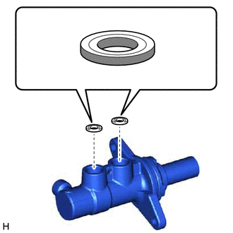
.png) | Lithium Soap Base Glycol Grease |
(b) Install the 2 master cylinder reservoir grommets to the brake master cylinder body.
4. INSTALL BRAKE MASTER CYLINDER RESERVOIR ASSEMBLY
(a) Secure the brake master cylinder body in a vise.
NOTICE:
Place aluminum plates on the vise to prevent damage to the brake master cylinder body.
(b) Install the brake master cylinder reservoir assembly to the brake master cylinder body.
NOTICE:
Do not drop the brake master cylinder reservoir assembly.
5. INSTALL BRAKE MASTER CYLINDER STRAIGHT PIN
| (a) Using a 5 mm pin punch and a hammer, tap in the brake master cylinder straight pin to secure the brake master cylinder reservoir assembly. |
|
.png)
(b) Remove the brake master cylinder sub-assembly from the vise.
READ NEXT:
 Removal
REMOVAL CAUTION / NOTICE / HINT The necessary procedures (adjustment, calibration, initialization or registration) that must be performed after parts are removed and installed, or replaced during brak
Adjustment
ADJUSTMENT PROCEDURE 1. INSPECT AND ADJUST BRAKE PEDAL HEIGHT (a) Remove the front door scuff plate LH. Click here (b) Remove the cowl side trim board LH. Click here (c) Remove the No. 1 instrumen
SEE MORE:
Hybrid/EV Powertrain Control Module Processor Unexpected Operation (P060694)
DTC SUMMARY MALFUNCTION DESCRIPTION The main CPU and sub CPU of the Hybrid vehicle control ECU monitor each other. The cause of this malfunction may be the following: Hybrid vehicle control ECU internal malfunction
Hybrid vehicle control ECU malfunction
DESCRIPTION The hybrid vehicle control E
Front Passenger Side Power Window Switch
ComponentsCOMPONENTS ILLUSTRATION *1 POWER WINDOW REGULATOR SWITCH ASSEMBLY *2 POWER WINDOW REGULATOR SWITCH ASSEMBLY WITH FRONT DOOR UPPER ARMREST BASE PANEL RemovalREMOVAL PROCEDURE 1. REMOVE POWER WINDOW REGULATOR SWITCH ASSEMBLY WITH FRONT DOOR UPPER ARMREST BASE PANEL Click here
