Lexus ES: Installation
INSTALLATION
PROCEDURE
1. INSPECT AND ADJUST BRAKE BOOSTER PUSH ROD
Click here .gif)
2. INSTALL BRAKE MASTER CYLINDER O-RING
(a) Install a new brake master cylinder O-ring to the brake master cylinder sub-assembly.
3. INSTALL BRAKE MASTER CYLINDER SUB-ASSEMBLY
NOTICE:
When installing a new brake master cylinder sub-assembly, remove the protectors from the master cylinder piston and outlet ports.
(a) Install the brake master cylinder sub-assembly to the brake booster assembly with the 2 nuts.
Torque:
12.5 N·m {127 kgf·cm, 9 ft·lbf}
NOTICE:
- The brake master cylinder sub-assembly requires careful handling. Do not drop or subject the brake master cylinder sub-assembly to any impact. Do not reuse a brake master cylinder sub-assembly that has been dropped.
- Do not hold the brake master cylinder sub-assembly by the master cylinder piston. Hold the brake master cylinder sub-assembly by its body or its reservoir when carrying it.
- Do not pull out the master cylinder piston.
- Do not strike or pinch the master cylinder piston, or cause any damage to the master cylinder piston by any other means.
- When installing the brake master cylinder sub-assembly to the brake booster assembly, or when removing the brake master cylinder sub-assembly from the brake booster assembly, make sure that the brake master cylinder sub-assembly is kept horizontal or with its tip facing downward (the master cylinder piston is facing upward) to prevent the master cylinder piston from falling out.
- Do not allow any foreign matter to contaminate the master cylinder piston. If any foreign matter gets on the master cylinder piston, remove it by using a piece of new and dry cloth. Do not use water or detergent. Then apply an even layer of lithium soap base glycol grease around the circumference (sliding part) of the master cylinder piston.
- Do not use any other types of grease.
- Do not kink or damage the brake lines.
- Do not allow the brake lines to twist or interfere with other parts or the vehicle body during tightening.
- Do not allow any foreign matter such as dirt or dust to enter the brake lines from the connecting parts.
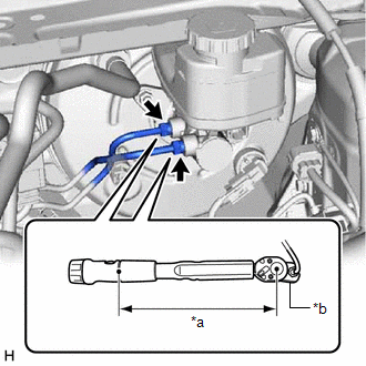
| (b) Using a union nut wrench, connect the 2 brake lines to the brake master cylinder sub-assembly. Torque: Specified tightening torque : 19.5 N·m {199 kgf·cm, 14 ft·lbf} NOTICE:
HINT:
|
|
(c) Connect the connector to the brake master cylinder sub-assembly.
4. BLEED BRAKE SYSTEM
Click here
5. INSTALL BATTERY
Click here
READ NEXT:
 Reassembly
REASSEMBLY PROCEDURE 1. INSTALL BRAKE MASTER CYLINDER RESERVOIR STRAINER 2. INSTALL BRAKE MASTER CYLINDER RESERVOIR FILLER CAP ASSEMBLY 3. INSTALL MASTER CYLINDER RESERVOIR GROMMET (a) Apply a light l
Removal
REMOVAL CAUTION / NOTICE / HINT The necessary procedures (adjustment, calibration, initialization or registration) that must be performed after parts are removed and installed, or replaced during brak
SEE MORE:
Components
COMPONENTS ILLUSTRATION *A for Driver Side *B for Front Passenger Side *1 COURTESY LIGHT ASSEMBLY *2 FRONT DOOR ILLUMINATION LIGHT (FRONT DOOR OUTSIDE HANDLE ASSEMBLY) *3 FRONT DOOR SERVICE HOLE COVER *4 FRONT DOOR TRIM BOARD SUB-ASSEMBLY *5 MULTIPLEX NETWORK MAST
Check For Intermittent Problems
CHECK FOR INTERMITTENT PROBLEMS NOTICE:
If the vehicle or vehicle controls are operated (for example, during initial inspection when the vehicle is brought in for repair) before operation history has been read and saved, the operation history information could be lost.
The Operation History fun
