Lexus ES: Disassembly
DISASSEMBLY
PROCEDURE
1. REMOVE FRONT DISC BRAKE PISTON
| (a) Place a piece of cloth between the front disc brake piston and front disc brake cylinder. |
|
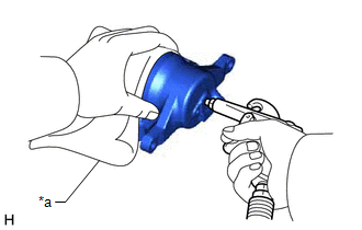
(b) Apply compressed air to remove the front disc brake piston from the front disc brake cylinder.
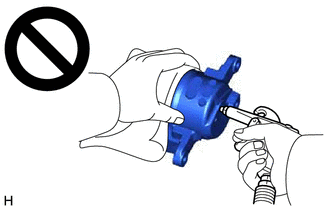
CAUTION:
- Do not hold the front disc brake cylinder with any part of your hand between the front disc brake cylinder and front disc brake piston.
- Do not place any part of your hand in front of the front disc brake piston when using compressed air as a severe injury may result.
NOTICE:
Do not allow any brake fluid to spatter.
2. REMOVE CYLINDER BOOT
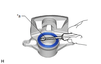
| (a) Using a screwdriver with its tip wrapped with protective tape, remove the cylinder boot from the front disc brake cylinder. NOTICE: Be careful not to damage the front disc brake cylinder. |
|
3. REMOVE PISTON SEAL
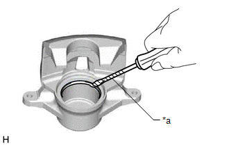
| (a) Using a screwdriver with its tip wrapped with protective tape, remove the piston seal from the front disc brake cylinder. NOTICE: Do not damage the inner surface or piston seal groove of the front disc brake cylinder. |
|
4. REMOVE FRONT DISC BRAKE BLEEDER PLUG CAP
(a) Remove the front disc brake bleeder plug cap from the front disc brake bleeder plug.
5. REMOVE FRONT DISC BRAKE BLEEDER PLUG
(a) Remove the front disc brake bleeder plug from the front disc brake cylinder.
READ NEXT:
 Inspection
INSPECTION PROCEDURE 1. INSPECT BRAKE CYLINDER AND PISTON (a) Check the front disc brake cylinder bore and front disc brake piston for rust and scoring. If necessary, replace the front disc brake cyli
Installation
INSTALLATION CAUTION / NOTICE / HINT NOTICE:
Immediately after installing the brake pads, the braking performance may be reduced. Always perform a road test in a safe place while paying attention t
Reassembly
REASSEMBLY PROCEDURE 1. TEMPORARILY TIGHTEN FRONT DISC BRAKE BLEEDER PLUG (a) Temporarily install the front disc brake bleeder plug to the front disc brake cylinder. HINT: Fully tighten the front disc
SEE MORE:
Fail-safe Chart
FAIL-SAFE CHART If a problem occurs in the power steering system, the power steering assist will be stopped or the amount of power assist will be decreased to protect the system. Power Steering System Malfunction Fail-safe Operation EPS warning light Buzzer
Torque sensor (rack and pi
Problem Symptoms Table
PROBLEM SYMPTOMS TABLE HINT:
Use the table below to help determine the cause of problem symptoms. If multiple suspected areas are listed, the potential causes of the symptoms are listed in order of probability in the "Suspected Area" column of the table. Check each symptom by checking the suspect
