Lexus ES: Installation
INSTALLATION
CAUTION / NOTICE / HINT
NOTICE:
- Immediately after installing the brake pads, the braking performance may be reduced. Always perform a road test in a safe place while paying attention to the surroundings.
- After replacing the front disc brake pads, the brake pedal may feel soft due to clearance between the front disc brake pads and front disc. Depress the brake pedal several times until the brake pedal feels firm.
- After replacing the front disc brake pads, always perform a road test to check the braking performance and check for vibrations.
- When the brake pedal is first depressed after replacing the brake pads or pushing back the disc brake piston, DTC C1214 may be stored. As there is no malfunction, clear the DTC. (for HV Model)
- While the auxiliary battery is connected, even if the power switch is off, the brake control system activates when the brake pedal is depressed or any door courtesy switch turns on. Therefore, when servicing the brake system components, do not operate the brake pedal or open/close the doors while the auxiliary battery is connected. (for HV Model)
HINT:
- Use the same procedure for the RH side and LH side.
- The following procedure is for the LH side.
PROCEDURE
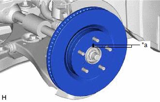
1. INSTALL FRONT DISC
| (a) Align the matchmarks of the front disc and front axle hub sub-assembly, and install the front disc. NOTICE: When replacing the front disc with a new one, select the installation position where the front disc has minimal runout. |
|
2. INSTALL FRONT DISC BRAKE CYLINDER MOUNTING
(a) Install the front disc brake cylinder mounting to the steering knuckle with the 2 bolts.
Torque:
107 N·m {1091 kgf·cm, 79 ft·lbf}
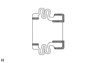
3. INSTALL FRONT DISC BRAKE BUSHING DUST BOOT
(a) Apply a light layer of lithium soap base glycol grease to the entire circumference of 2 new front disc brake bushing dust boots.
HINT:
Apply more than 0.3 g (0.01 oz) of lithium soap base glycol grease to each front disc brake bushing dust boot.
 | Lithium Soap Base Glycol Grease |
(b) Install the 2 front disc brake bushing dust boots to the front disc brake cylinder mounting.
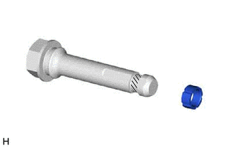
4. INSTALL FRONT DISC BRAKE CYLINDER SLIDE PIN
(a) Apply a light layer of lithium soap base glycol grease to the contact surface of the front disc brake cylinder slide pin (lower side) and a new front disc brake cylinder slide bushing.
| | Lithium Soap Base Glycol Grease |
(b) Install the front disc brake cylinder slide bushing to the front disc brake cylinder slide pin (lower side).
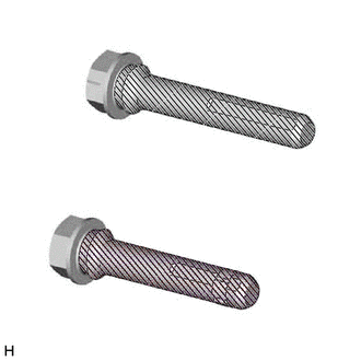
(c) Apply a light layer of lithium soap base glycol grease to the sliding part and the sealing surfaces of the 2 front disc brake cylinder slide pins.
| | Lithium Soap Base Glycol Grease |
(d) Install the 2 front disc brake cylinder slide pins to the front disc brake cylinder mounting.
(e) Push each front disc brake cylinder slide pin into the front disc brake bushing dust boot to engage the pin to the boot.
5. INSTALL FRONT DISC BRAKE PAD SUPPORT PLATE
| (a) Install the 4 front disc brake pad support plates to the front disc brake cylinder mounting. NOTICE: Be sure to install each front disc brake pad support plate in the correct position and direction. |
|

6. INSTALL FRONT DISC BRAKE ANTI-SQUEAL SHIM KIT
Click here .gif)
7. INSTALL FRONT DISC BRAKE PAD
(a) Install the 2 front disc brake pads to the front disc brake cylinder mounting.
NOTICE:
- Keep the friction surfaces of the front disc brake pads and front disc free from oil and grease.
- Install the front disc brake pad so that the front disc brake pad wear indicator plate is mounted on the upper side of the vehicle.
8. INSTALL FRONT DISC BRAKE CYLINDER ASSEMBLY
(a) Hold each front disc brake cylinder slide pin and install the front disc brake cylinder assembly to the front disc brake cylinder mounting with the 2 bolts.
Torque:
34.3 N·m {350 kgf·cm, 25 ft·lbf}
9. CONNECT FRONT FLEXIBLE HOSE
(a) Connect the front flexible hose to the front disc brake cylinder assembly with a new union bolt and a new gasket.
Torque:
29.4 N·m {300 kgf·cm, 22 ft·lbf}
NOTICE:
Install the front flexible hose lock securely into the lock hole in the front disc brake cylinder assembly.
10. CONNECT CABLE TO NEGATIVE AUXILIARY BATTERY TERMINAL (for HV Model)
(a) Connect the reservoir level switch connector.
(b) Connect the cable to the negative (-) auxiliary battery terminal.
Click here
(c) Perform the following procedure if air bleeding is not necessary:
(1) Turn the power switch on (READY).
(2) Depress the brake pedal and release it.
(3) Clear the DTCs.
Click here
11. BLEED BRAKE LINE
for HV Model: Click here
for Gasoline Model: Click here
12. INSTALL FRONT WHEEL
Click here
READ NEXT:
 Reassembly
REASSEMBLY PROCEDURE 1. TEMPORARILY TIGHTEN FRONT DISC BRAKE BLEEDER PLUG (a) Temporarily install the front disc brake bleeder plug to the front disc brake cylinder. HINT: Fully tighten the front disc
Removal
REMOVAL CAUTION / NOTICE / HINT The necessary procedures (adjustment, calibration, initialization, or registration) that must be performed after parts are removed and installed, or replaced during fro
Front Disc Brake Pad
ComponentsCOMPONENTS ILLUSTRATION *1 FRONT DISC BRAKE ANTI-SQUEAL SHIM KIT *2 FRONT DISC BRAKE PAD *3 FRONT DISC BRAKE CYLINDER ASSEMBLY *4 FRONT DISC BRAKE PAD WEAR INDICATOR PLA
SEE MORE:
Left Front Wheel ABS Hold Solenoid Control Circuit Short to Battery (C12A512,...,C12B049)
DESCRIPTION The ABS solenoid relay and solenoid valves are built into the brake actuator assembly. The front solenoid valve LH controls the brake fluid pressure of the front wheel cylinder LH of the vehicle. When this DTC is stored, the fail-safe function operates and the ABS solenoid relay is turne
Removal
REMOVAL
PROCEDURE
1. REMOVE BATTERY SERVICE HOLE COVER
(a) Remove the clip.
Remove in this Direction
(b) Disengage the 7 claws as shown in the illustration.
(c) Disengage the guide to remove the battery service hole cover as shown in
the illustration.
