Lexus ES: Reassembly
REASSEMBLY
PROCEDURE
1. TEMPORARILY TIGHTEN FRONT DISC BRAKE BLEEDER PLUG
(a) Temporarily install the front disc brake bleeder plug to the front disc brake cylinder.
HINT:
Fully tighten the front disc brake bleeder plug after bleeding the system.
2. INSTALL FRONT DISC BRAKE BLEEDER PLUG CAP
(a) Install the front disc brake bleeder plug cap to the front disc brake bleeder plug.
3. INSTALL PISTON SEAL
(a) Apply a light layer of lithium soap base glycol grease to the entire circumference of a new piston seal.
.png) | Lithium Soap Base Glycol Grease |
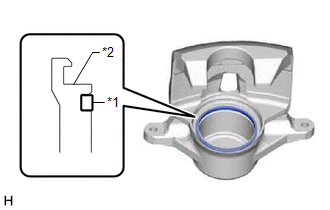
| (b) Install the piston seal to the front disc brake cylinder. NOTICE: Securely install the piston seal into the groove of the front disc brake cylinder. |
|
4. INSTALL FRONT DISC BRAKE PISTON
(a) Apply a light layer of lithium soap base glycol grease to the entire circumference of a new cylinder boot.
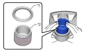
| *1 | Cylinder Boot |
| *2 | Front Disc Brake Piston |
| | Lithium Soap Base Glycol Grease |
(b) Apply a light layer of lithium soap base glycol grease to the contact surfaces of the front disc brake piston.
(c) Install the cylinder boot to the front disc brake piston.
NOTICE:
Securely install the cylinder boot into the groove of the front disc brake piston.
(d) Install the front disc brake piston to the front disc brake cylinder.
NOTICE:
Do not forcibly install the front disc brake piston into the front disc brake cylinder.
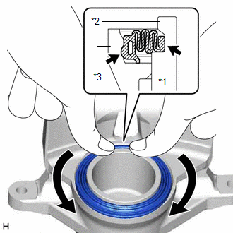
5. INSTALL CYLINDER BOOT
| (a) Install the cylinder boot to the front disc brake cylinder as shown in the illustration. NOTICE:
|
|
READ NEXT:
 Removal
REMOVAL CAUTION / NOTICE / HINT The necessary procedures (adjustment, calibration, initialization, or registration) that must be performed after parts are removed and installed, or replaced during fro
Front Disc Brake Pad
ComponentsCOMPONENTS ILLUSTRATION *1 FRONT DISC BRAKE ANTI-SQUEAL SHIM KIT *2 FRONT DISC BRAKE PAD *3 FRONT DISC BRAKE CYLINDER ASSEMBLY *4 FRONT DISC BRAKE PAD WEAR INDICATOR PLA
SEE MORE:
On-vehicle Inspection
ON-VEHICLE INSPECTION CAUTION / NOTICE / HINT The necessary procedures (adjustment, calibration, initialization, or registration) that must be performed after parts are removed and installed, or replaced during rear axle hub and bearing assembly on-vehicle inspection are shown below. Necessary Proce
System Diagram
SYSTEM DIAGRAM Communication Table Sender Receiver Signal Line Certification ECU (Smart Key ECU Assembly) Main Body ECU (Multiplex Network Body ECU) Luggage compartment door lock assembly open operation signal CAN
