Lexus ES: Ignition Coil And Spark Plug
Removal
REMOVAL
CAUTION / NOTICE / HINT
The necessary procedures (adjustment, calibration, initialization or registration) that must be performed after parts are removed and installed, or replaced during ignition coil assembly or spark plug removal/installation are shown below.
Necessary Procedures After Parts Removed/Installed/Replaced| Replaced Part or Performed Procedure | Necessary Procedure | Effect/Inoperative Function when Necessary Procedure not Performed | Link |
|---|---|---|---|
| Inspection after repair |
| |
NOTICE:
This procedure includes the removal of small-head bolts. Refer to Small-Head Bolts of Basic Repair Hint to identify the small-head bolts.
Click here .gif)
PROCEDURE
1. REMOVE NO. 1 ENGINE COVER SUB-ASSEMBLY
Click here
2. REMOVE IGNITION COIL ASSEMBLY
| (a) Disconnect the 4 ignition coil assembly connectors. |
|
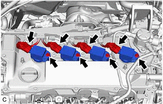
(b) Using an 8 mm socket wrench, remove the 4 bolts and 4 ignition coil assemblies from the cylinder head cover sub-assembly.
NOTICE:
If an ignition coil assembly has been struck or dropped, replace it.
HINT:
Arrange the removed parts in the correct order.
3. REMOVE SPARK PLUG
Click here
Installation
INSTALLATION
CAUTION / NOTICE / HINT
NOTICE:
This procedure includes the installation of small-head bolts. Refer to Small-Head Bolts of Basic Repair Hint to identify the small-head bolts.
Click here .gif)
PROCEDURE
1. INSTALL SPARK PLUG
Click here
2. INSTALL IGNITION COIL ASSEMBLY
HINT:
Perform "Inspection After Repair" after replacing an ignition coil assembly.
Click here
(a) Using an 8 mm socket wrench, install the 4 ignition coil assemblies to the cylinder head cover sub-assembly with the 4 bolts.
Torque:
7.5 N·m {76 kgf·cm, 66 in·lbf}
NOTICE:
If an ignition coil assembly has been struck or dropped, replace it.
HINT:
Install the same parts to their original positions.
(b) Connect the 4 ignition coil assembly connectors.
3. INSTALL NO. 1 ENGINE COVER SUB-ASSEMBLY
Click here
4. PERFORM INITIALIZATION
(a) Perform "Inspection After Repair" after replacing an ignition coil assembly or spark plug.
Click here
READ NEXT:
 Parts Location
PARTS LOCATION ILLUSTRATION *1 ECM *2 NO. 1 ENGINE ROOM RELAY BLOCK AND NO. 1 JUNCTION BLOCK ASSEMBLY - INJ FUSE *3 IGNITION COIL ASSEMBLY *4 SPARK PLUG
System Diagram
SYSTEM DIAGRAM
SEE MORE:
Installation
INSTALLATION CAUTION / NOTICE / HINT HINT:
Use the same procedure for the RH side and LH side.
The following procedure is for the LH side.
PROCEDURE 1. INSTALL HOOD SUPPORT BRACKET (a) Engage the guide. (b) Install the hood support bracket with the bolt. Torque: 17.5 N·m {178 kgf·cm, 13 f
Brake Switch "A" Circuit Short to Ground (P057111)
DESCRIPTION The skid control ECU (brake actuator assembly) receives stop light switch assembly signals and uses them to determine whether or not the brakes are applied. When the brake pedal is depressed and no signal is received from the stop light switch assembly, this DTC is output. DTC No. D
