Lexus ES: Removal
REMOVAL
CAUTION / NOTICE / HINT
The necessary procedures (adjustment, calibration, initialization or registration) that must be performed after parts are removed and installed, or replaced during ECM removal/installation are shown below.
Necessary Procedures After Parts Removed/Installed/Replaced| Replaced Part or Performed Procedure | Necessary Procedure | Effect/Inoperative Function when Necessary Procedure not Performed | Link |
|---|---|---|---|
| Battery terminal is disconnected/reconnected | Perform steering sensor zero point calibration | Lane Control System (for Gasoline Model) | |
| Pre-collision System (for Gasoline Model) | |||
| Parking Support Brake System (for Gasoline Model)*1 | |||
| Lighting System (for Gasoline Model) | |||
| Memorize steering angle neutral point | Parking Assist Monitor System (for Gasoline Model) | | |
| Panoramic View Monitor System (for Gasoline Model) | | ||
| Initialize power trunk lid system | Power Trunk Lid System (for Gasoline Model) | | |
| Replacement of ECM | Vehicle Identification Number (VIN) registration | MIL comes on | |
| ECU communication ID registration (Immobiliser system) | Engine start function | | |
| Replacement of ECM (If transaxle compensation code read from ECM) |
|
| |
| Replacement of ECM (If transaxle compensation code not read from ECM) |
| ||
| Replacement of ECM | Code registration (Smart access system with push-button start (for Start Function, Gasoline Model) |
| |
-
*1: When performing learning using the Techstream.
Click here
.gif)
- *2: Not necessary when ECM replaced with new one
NOTICE:
- After the engine switch is turned off, the radio receiver assembly records various types of memory and settings. As a result, after turning the engine switch off, make sure to wait at least 85 seconds before disconnecting the cable from the negative (-) battery terminal. (for Audio and Visual System)
- After the engine switch is turned off, the radio receiver assembly records various types of memory and settings. As a result, after turning the engine switch off, make sure to wait at least 85 seconds before disconnecting the cable from the negative (-) battery terminal. (for Navigation System)
- If the ECM has been struck or dropped, replace it.
-
Perform Vehicle Identification Number (VIN) registration when replacing the ECM.
Click here
.gif)
PROCEDURE
1. PRECAUTION
NOTICE:
After turning the engine switch off, waiting time may be required before disconnecting the cable from the negative (-) battery terminal. Therefore, make sure to read the disconnecting the cable from the negative (-) battery terminal notices before proceeding with work.
2. DISCONNECT CABLE FROM NEGATIVE BATTERY TERMINAL
Click here .gif)
3. REMOVE COOL AIR INTAKE DUCT SEAL
Click here .gif)
4. REMOVE INLET AIR CLEANER ASSEMBLY
Click here .gif)
5. REMOVE AIR CLEANER ASSEMBLY WITH AIR CLEANER HOSE
Click here .gif)
6. REMOVE ECM
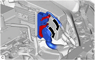
| (a) Rotate the 2 levers while pushing the locks, and disconnect the 2 ECM connectors. NOTICE: After disconnecting the ECM connectors, make sure that dirt, water and other foreign matter does not contact the connecting parts of the ECM connectors. |
|
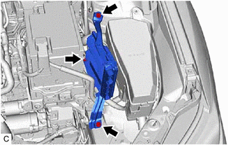
| (b) Remove the 2 bolts, nut and ECM. NOTICE: If the ECM has been struck or dropped, replace it. |
|
7. REMOVE NO. 1 ECM BRACKET
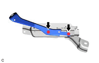
| (a) Remove the 2 screws and No. 1 ECM bracket from the ECM. |
|
8. REMOVE NO. 2 ECM BRACKET
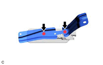
| (a) Remove the 2 screws and No. 2 ECM bracket from the ECM. |
|


