Lexus ES: Components
COMPONENTS
ILLUSTRATION
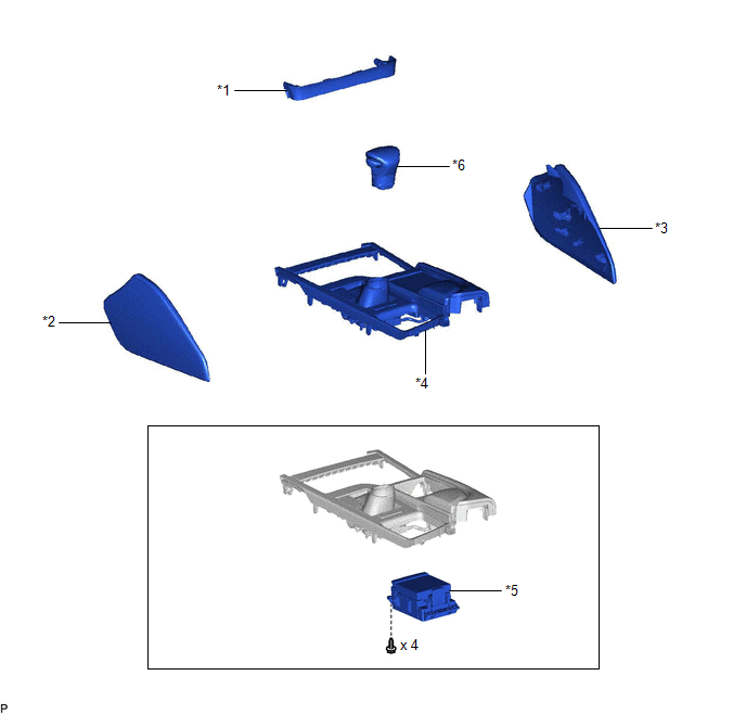
| *1 | CENTER INSTRUMENT CLUSTER FINISH PANEL SUB-ASSEMBLY | *2 | INSTRUMENT PANEL FINISH PANEL END LH |
| *3 | INSTRUMENT PANEL FINISH PANEL END RH | *4 | REAR UPPER CONSOLE PANEL SUB-ASSEMBLY |
| *5 | REMOTE OPERATION CONTROLLER ASSEMBLY | *6 | SHIFT LEVER KNOB SUB-ASSEMBLY |
READ NEXT:
 Installation
INSTALLATION PROCEDURE 1. INSTALL REMOTE OPERATION CONTROLLER ASSEMBLY (a) Install the remote operation controller assembly with the 4 screws as shown in the illustration. Install in this Direc
Installation
INSTALLATION PROCEDURE 1. INSTALL REMOTE OPERATION CONTROLLER ASSEMBLY (a) Install the remote operation controller assembly with the 4 screws as shown in the illustration. Install in this Direc
Removal
REMOVAL PROCEDURE 1. REMOVE INSTRUMENT PANEL FINISH PANEL END LH Click here 2. REMOVE INSTRUMENT PANEL FINISH PANEL END RH Click here 3. REMOVE CENTER INSTRUMENT CLUSTER FINISH PANEL SUB-ASSEMBLY
SEE MORE:
Kick Sensor Circuit (B2205)
DESCRIPTION DTC B2205 is output when the luggage closer motor assembly detects that the kick door control sensor is stuck on. DTC No. Detection Item DTC Detection Condition Trouble Area B2205 Kick Sensor Circuit One of the following conditions is met for approximately 60 seconds or
Vehicle Speed Sensor (B2415)
DESCRIPTION The headlight ECU sub-assembly LH receives speed signals from the skid control ECU (brake actuator assembly) via CAN communication and performs light control. for LED Type Turn Signal Light DTC No. Detection Item DTC Detection Condition Trouble Area DTC Output from B2415
© 2016-2026 Copyright www.lexguide.net
