Lexus ES: Components
COMPONENTS
ILLUSTRATION
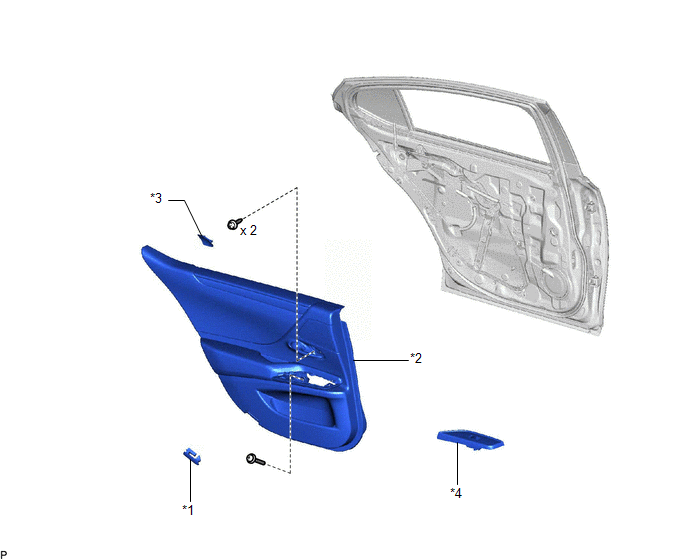
| *1 | COURTESY LIGHT ASSEMBLY | *2 | REAR DOOR TRIM BOARD SUB-ASSEMBLY |
| *3 | REAR DOOR TRIM UPPER PAD | *4 | REAR POWER WINDOW REGULATOR SWITCH ASSEMBLY WITH REAR DOOR UPPER ARMREST BASE PANEL |
ILLUSTRATION
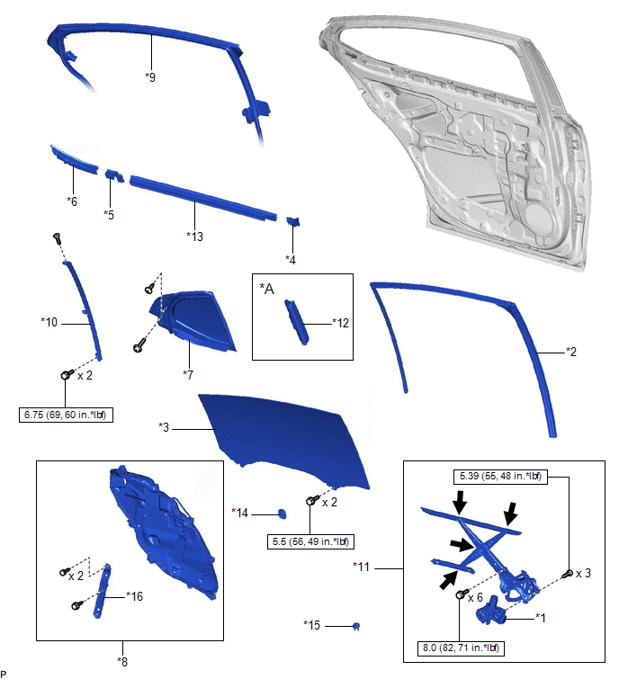
| *A | w/ Rear Door Sunshade | - | - |
| *1 | POWER WINDOW REGULATOR MOTOR ASSEMBLY | *2 | REAR DOOR GLASS RUN |
| *3 | REAR DOOR GLASS SUB-ASSEMBLY | *4 | REAR DOOR NO. 2 SERVICE HOLE COVER |
| *5 | REAR DOOR NO. 2 VENT SEAL | *6 | REAR DOOR PANEL PROTECTOR |
| *7 | REAR DOOR QUARTER WINDOW GLASS SUB-ASSEMBLY | *8 | REAR DOOR SERVICE HOLE COVER |
| *9 | REAR DOOR WEATHERSTRIP | *10 | REAR DOOR WINDOW DIVISION BAR SUB-ASSEMBLY |
| *11 | REAR DOOR WINDOW REGULATOR ASSEMBLY | *12 | REAR SIDE CURTAIN ASSEMBLY |
| *13 | REAR DOOR INNER GLASS WEATHERSTRIP | *14 | HOLE PLUG |
| *15 | REAR DOOR NO. 3 SERVICE HOLE COVER | *16 | BRACKET |
.png) | N*m (kgf*cm, ft.*lbf): Specified torque | .png) | MP grease |
READ NEXT:
 Removal
REMOVAL CAUTION / NOTICE / HINT The necessary procedures (adjustment, calibration, initialization, or registration) that must be performed after parts are removed and installed, or replaced during pow
Inspection
INSPECTION PROCEDURE 1. INSPECT POWER WINDOW REGULATOR MOTOR ASSEMBLY (FOR REAR LH DOOR) (a) Connect a positive (+) lead from the auxiliary battery to connector terminal 2. NOTICE: Do not connect a
Installation
INSTALLATION CAUTION / NOTICE / HINT HINT:
Use the same procedure for the RH side and LH side.
The following procedure is for the LH side.
PROCEDURE 1. PRECAUTION NOTICE: After turning the eng
SEE MORE:
Installation
INSTALLATION PROCEDURE 1. INSTALL MASS AIR FLOW METER SUB-ASSEMBLY HINT: Perform "Inspection After Repair" after replacing the mass air flow meter sub-assembly. Click here (a) Install the mass air flow meter sub-assembly to the air cleaner cap sub-assembly with the 2 screws. NOTICE:
If the mas
Steering Angle Midpoint Initial Setting Incomplete (C1AEA)
DESCRIPTION When the clearance warning ECU assembly detects that the steering angle neutral point memorization is incomplete during self diagnosis, C1AEA is stored. DTC No. Detection Item DTC Detection Condition Trouble Area C1AEA Steering Angle Midpoint Initial Setting Incomplete S
