Lexus ES: Components
COMPONENTS
ILLUSTRATION
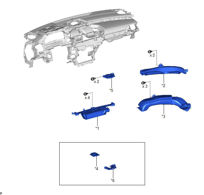
| *1 | DEFROSTER NOZZLE ASSEMBLY | *2 | NO. 2 SIDE DEFROSTER NOZZLE DUCT |
| *3 | NO. 3 HEATER TO REGISTER DUCT | *4 | TELEPHONE AND GPS ANTENNA ASSEMBLY |
| *5 | TELEPHONE AND GPS ANTENNA ASSEMBLY WITH BRACKET | *6 | TELEPHONE AND GPS ANTENNA BRACKET |
READ NEXT:
 Installation
INSTALLATION PROCEDURE 1. INSTALL TELEPHONE AND GPS ANTENNA BRACKET 2. INSTALL TELEPHONE AND GPS ANTENNA ASSEMBLY (a) Engage the 6 guides and 2 claws to install the telephone and GPS antenna assembly
Removal
REMOVAL CAUTION / NOTICE / HINT The necessary procedures (adjustment, calibration, initialization, or registration) that must be performed after parts are removed and installed, or replaced during tel
SEE MORE:
Internal Control Module Software Incompatibility Not Programmed (U030051)
DESCRIPTION The forward recognition camera receives the vehicle information from the ECM via CAN communication. If the forward recognition camera cannot store the vehicle information sent from the ECM, it stores DTC U030051. DTC No. Detection Item DTC Detection Condition Trouble Area U0
Components
COMPONENTS ILLUSTRATION *1 FRONT FENDER APRON SEAL RH *2 V-BANK COVER SUB-ASSEMBLY N*m (kgf*cm, ft.*lbf): Specified torque - - ILLUSTRATION *1 CAMSHAFT TIMING GEAR BOLT *2 O-RING *3 CAMSHAFT TIMING OIL CONTROL SOLENOID ASSEMBLY (for Exhaust Side of Bank 1) -
© 2016-2026 Copyright www.lexguide.net
